Wednesday, January 31, 2024

STM32F103R6 DHT-11 Temperature and Humidity Sensor with LCD Example

The DHT-11 is a temperature and humidity sensor that use only one bidirectional serial data pin. The converted temperature is between 0 and 50 degree Celsius. Its working humidity is between 20 and 90 RH.

STM32F103R6 DHT-11 Temperature and Humidity Sensor with LCD Example
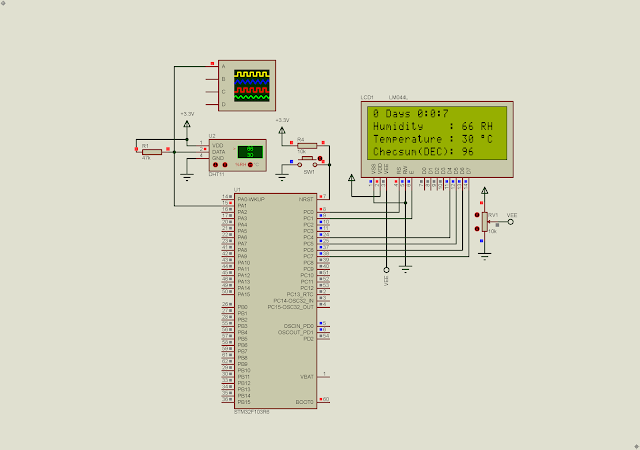
Program Simulation in Proteus

The sensor data is very easy to decode using only ones microprocessor digital pin. I don't show the details of serial data transmission here. You can see the post that use a PIC1F84A to decode the signal

STM32F103R6 DHT-11 Temperature and Humidity Sensor with LCD Example
DHT-11 Humidity & Temperature Sensor

We can get this sensor at local electronics parts store around 1USD. In this example, I use the STM32F103R6 to read environmental data from this sensor. The temperature and humidity will show on a 20x4 character LCD.

  1. /* USER CODE BEGIN Header */
  2. /**
  3.   ******************************************************************************
  4.   * @file : main.c
  5.   * @brief : Main program body
  6.   ******************************************************************************
  7.   * @attention
  8.   *
  9.   * <h2><center>&copy; Copyright (c) 2023 STMicroelectronics.
  10.   * All rights reserved.</center></h2>
  11.   *
  12.   * This software component is licensed by ST under BSD 3-Clause license,
  13.   * the "License"; You may not use this file except in compliance with the
  14.   * License. You may obtain a copy of the License at:
  15.   * opensource.org/licenses/BSD-3-Clause
  16.   *
  17.   ******************************************************************************
  18.   */
  19. /* USER CODE END Header */
  20. /* Includes ------------------------------------------------------------------*/
  21. #include "main.h"
  22. #include "lcd4bits.h"
  23.  
  24. /* Private function prototypes -----------------------------------------------*/
  25. void SystemClock_Config(void);
  26. static void MX_GPIO_Init(void);
  27.  
  28. void delay_us(uint8_t dTime){
  29. for(uint8_t i=0;i<dTime;i++) asm("nop");
  30. }
  31.  
  32.  
  33. uint8_t *readDHT11(void){
  34. uint8_t *dht11;
  35. for(uint8_t i=0;i<5;i++) dht11[i]=0;
  36. HAL_GPIO_WritePin(GPIOA,DQ_Pin,GPIO_PIN_SET);
  37. HAL_Delay(10);
  38. HAL_GPIO_WritePin(GPIOA,DQ_Pin,GPIO_PIN_RESET);
  39. HAL_Delay(18);
  40. HAL_GPIO_WritePin(GPIOA,DQ_Pin,GPIO_PIN_SET);
  41. delay_us(45);
  42.  
  43. while(HAL_GPIO_ReadPin(GPIOA,DQ_Pin)==GPIO_PIN_RESET);
  44. delay_us(10);
  45. while(HAL_GPIO_ReadPin(GPIOA,DQ_Pin)==GPIO_PIN_SET);
  46. delay_us(10);
  47.  
  48. for(uint8_t i=0;i<5;i++){
  49. for(uint8_t j=0;j<8;j++){
  50. delay_us(5);
  51. while(HAL_GPIO_ReadPin(GPIOA,DQ_Pin)==GPIO_PIN_RESET);
  52. delay_us(65);
  53. if(HAL_GPIO_ReadPin(GPIOA,DQ_Pin)==GPIO_PIN_SET) {
  54. while(HAL_GPIO_ReadPin(GPIOA,DQ_Pin)==GPIO_PIN_SET);
  55. dht11[i]|=(1<<7-j);
  56. }
  57. }
  58. delay_us(5);
  59. }
  60. delay_us(10);
  61. /*Check Sum Checking dht11[4] is checksum byte*/
  62. //uint8_t checksum=dht11[0]+dht11[1]+dht11[2]+dht11[3];
  63. uint8_t checksum=0;
  64. for(uint8_t i=0;i<4;i++) checksum+=dht11[i];
  65. if(checksum!=dht11[4]){
  66. for(uint8_t i=0;i<5;i++) dht11[i]=0;
  67. return;
  68. }
  69. return dht11;
  70. }
  71.  
  72. /**
  73.   * @brief The application entry point.
  74.   * @retval int
  75.   */
  76. int main(void)
  77. {
  78.  
  79. /* Reset of all peripherals, Initializes the Flash interface and the Systick. */
  80. HAL_Init();
  81.  
  82. /* Configure the system clock */
  83. SystemClock_Config();
  84.  
  85. /* Initialize all configured peripherals */
  86. MX_GPIO_Init();
  87. lcdInit();
  88. lcdClear();
  89.  
  90. lcdXY(1,1);
  91. lcdStr("STM32F103R6 DHT11");
  92. uint8_t *temp,*dht11;
  93. uint8_t seconds=0,minutes=0,hours=0;
  94. uint16_t days=0;;
  95. HAL_Delay(1500);
  96. lcdClear();
  97. HAL_Delay(5);
  98. //lcdXY(5,1);
  99. //lcdStr("Sensor Data:");
  100. lcdXY(1,2);
  101. lcdStr("Humidity : ");
  102. lcdXY(1,3);
  103. lcdStr("Temperature : ");
  104. lcdXY(1,4);
  105. lcdStr("Checsum(DEC): ");
  106. lcdCmd(0x0C);
  107. HAL_Delay(5);
  108.  
  109. /* Infinite loop */
  110. /* USER CODE BEGIN WHILE */
  111. while (1)
  112. {
  113. dht11=readDHT11();
  114.  
  115. seconds++;
  116. if(seconds>=60) {minutes++;seconds=0;}
  117. if(minutes>=60) {hours++; minutes=0;}
  118. if(hours>=24) {days++; hours=0;}
  119. sprintf(temp,"%d Days %d:%d:%d ",days,hours,minutes,seconds%60);
  120. lcdXY(1,1);
  121. lcdStr(temp);
  122.  
  123. sprintf(temp,"%d RH ",dht11[0]);
  124. lcdXY(15,2);
  125. lcdStr(temp);
  126.  
  127. sprintf(temp,"%d %cC ",dht11[2],223);
  128. lcdXY(15,3);
  129. lcdStr(temp);
  130.  
  131. sprintf(temp,"%d ",dht11[4]);
  132. lcdXY(15,4);
  133. lcdStr(temp);
  134.  
  135. HAL_Delay(700);
  136. }
  137. /* USER CODE END 3 */
  138. }
  139.  
  140. /**
  141.   * @brief System Clock Configuration
  142.   * @retval None
  143.   */
  144. void SystemClock_Config(void)
  145. {
  146. RCC_OscInitTypeDef RCC_OscInitStruct = {0};
  147. RCC_ClkInitTypeDef RCC_ClkInitStruct = {0};
  148.  
  149. /** Initializes the RCC Oscillators according to the specified parameters
  150.   * in the RCC_OscInitTypeDef structure.
  151.   */
  152. RCC_OscInitStruct.OscillatorType = RCC_OSCILLATORTYPE_HSI;
  153. RCC_OscInitStruct.HSIState = RCC_HSI_ON;
  154. RCC_OscInitStruct.HSICalibrationValue = RCC_HSICALIBRATION_DEFAULT;
  155. RCC_OscInitStruct.PLL.PLLState = RCC_PLL_ON;
  156. RCC_OscInitStruct.PLL.PLLSource = RCC_PLLSOURCE_HSI_DIV2;
  157. RCC_OscInitStruct.PLL.PLLMUL = RCC_PLL_MUL8;
  158. if (HAL_RCC_OscConfig(&RCC_OscInitStruct) != HAL_OK)
  159. {
  160. Error_Handler();
  161. }
  162. /** Initializes the CPU, AHB and APB buses clocks
  163.   */
  164. RCC_ClkInitStruct.ClockType = RCC_CLOCKTYPE_HCLK|RCC_CLOCKTYPE_SYSCLK
  165. |RCC_CLOCKTYPE_PCLK1|RCC_CLOCKTYPE_PCLK2;
  166. RCC_ClkInitStruct.SYSCLKSource = RCC_SYSCLKSOURCE_PLLCLK;
  167. RCC_ClkInitStruct.AHBCLKDivider = RCC_SYSCLK_DIV1;
  168. RCC_ClkInitStruct.APB1CLKDivider = RCC_HCLK_DIV1;
  169. RCC_ClkInitStruct.APB2CLKDivider = RCC_HCLK_DIV1;
  170.  
  171. if (HAL_RCC_ClockConfig(&RCC_ClkInitStruct, FLASH_LATENCY_1) != HAL_OK)
  172. {
  173. Error_Handler();
  174. }
  175. }
  176.  
  177. /**
  178.   * @brief GPIO Initialization Function
  179.   * @param None
  180.   * @retval None
  181.   */
  182. static void MX_GPIO_Init(void)
  183. {
  184. GPIO_InitTypeDef GPIO_InitStruct = {0};
  185.  
  186. /* GPIO Ports Clock Enable */
  187. __HAL_RCC_GPIOC_CLK_ENABLE();
  188. __HAL_RCC_GPIOA_CLK_ENABLE();
  189.  
  190. /*Configure GPIO pin Output Level */
  191. HAL_GPIO_WritePin(GPIOC, GPIO_PIN_0|GPIO_PIN_1|GPIO_PIN_2|GPIO_PIN_3
  192. |GPIO_PIN_4|GPIO_PIN_5|GPIO_PIN_6|GPIO_PIN_7, GPIO_PIN_RESET);
  193.  
  194. /*Configure GPIO pin Output Level */
  195. HAL_GPIO_WritePin(DQ_GPIO_Port, DQ_Pin, GPIO_PIN_RESET);
  196.  
  197. /*Configure GPIO pins : PC0 PC1 PC2 PC3
  198.   PC4 PC5 PC6 PC7 */
  199. GPIO_InitStruct.Pin = GPIO_PIN_0|GPIO_PIN_1|GPIO_PIN_2|GPIO_PIN_3
  200. |GPIO_PIN_4|GPIO_PIN_5|GPIO_PIN_6|GPIO_PIN_7;
  201. GPIO_InitStruct.Mode = GPIO_MODE_OUTPUT_PP;
  202. GPIO_InitStruct.Pull = GPIO_NOPULL;
  203. GPIO_InitStruct.Speed = GPIO_SPEED_FREQ_LOW;
  204. HAL_GPIO_Init(GPIOC, &GPIO_InitStruct);
  205.  
  206. /*Configure GPIO pin : DQ_Pin */
  207. GPIO_InitStruct.Pin = DQ_Pin;
  208. GPIO_InitStruct.Mode = GPIO_MODE_OUTPUT_OD;
  209. GPIO_InitStruct.Pull = GPIO_NOPULL;
  210. GPIO_InitStruct.Speed = GPIO_SPEED_FREQ_HIGH;
  211. HAL_GPIO_Init(DQ_GPIO_Port, &GPIO_InitStruct);
  212.  
  213. }
  214.  
  215. /* USER CODE BEGIN 4 */
  216.  
  217. /* USER CODE END 4 */
  218.  
  219. /**
  220.   * @brief This function is executed in case of error occurrence.
  221.   * @retval None
  222.   */
  223. void Error_Handler(void)
  224. {
  225. /* USER CODE BEGIN Error_Handler_Debug */
  226. /* User can add his own implementation to report the HAL error return state */
  227. __disable_irq();
  228. while (1)
  229. {
  230. }
  231. /* USER CODE END Error_Handler_Debug */
  232. }
  233.  
  234. #ifdef USE_FULL_ASSERT
  235. /**
  236.   * @brief Reports the name of the source file and the source line number
  237.   * where the assert_param error has occurred.
  238.   * @param file: pointer to the source file name
  239.   * @param line: assert_param error line source number
  240.   * @retval None
  241.   */
  242. void assert_failed(uint8_t *file, uint32_t line)
  243. {
  244. /* USER CODE BEGIN 6 */
  245. /* User can add his own implementation to report the file name and line number,
  246.   ex: printf("Wrong parameters value: file %s on line %d\r\n", file, line) */
  247. /* USER CODE END 6 */
  248. }
  249. #endif /* USE_FULL_ASSERT */
  250.  
  251. /************************ (C) COPYRIGHT STMicroelectronics *****END OF FILE****/
  252.  

Click here to download its source file.

Monday, December 25, 2023

STM32F103R6 ADC1 LM35 LCD Example

Overview

LM35 is an analog temperature to voltage converter. Its analog voltage output is linear with the environment temperature. Without a microprocessor's ADC module we can calculate manually using an AVM or a DVM, and self calculation.

STM32F103R6 ADC1 LM35 LCD Example
Program Simulation In Proteus

For some electronics hobbyist project without micro-controller, an ICL7107 analog to BCD 7-segment display output is applied. We can use LM35 as an analog input with an adjustment to a correct temperature value.

STM32F103R6 ADC1 LM35 LCD Example
Features and Applications

A small micro-controller with an internal ADC such as PIC16F818, or even an Arduino can easily read and interpret temperature value in degree Celsius.

STM32F103R6 ADC1 LM35 LCD Example
Device Information

This temperature sensor typically need a DC power supply between +4 and +20V. A +5VDC stable power supply is common with most of TTL type 8-bit micro-controllers.

STM32F103R6 Programming with STM32CubeIDE

An STM32F103R6 is among the STM32 ARM Cortex M3 micro-controller family with low power consumption and low cost. This device operates in 3.3VDC mode. Some of I/O pin tolerates with a +5VDC input voltage.

LM35 and character LCD requires a stable +5VDC power source to operate. This source can be driven from a USB power bus, or an additional voltage regulator. However the STM32F103R6 must supplied from a +3.3V only power source.

In this example, the STM32F103R6 continuously read the analog temperature value from the sensor. It will be display on a 16x2 HD44780 character LCD in degree Celsius.

I configure its I/O pins as follow.

STM32F103R6 ADC1 LM35 LCD Example
Pinout and Configuration

 I select the ADC1 module with preferred configurations.

STM32F103R6 ADC1 LM35 LCD Example

ADC1 Configurations

System Core configuration is optional. We will need to generate source code to get a C system configuration in its main.c file.

  1. /* USER CODE BEGIN Header */
  2. /**
  3.   ******************************************************************************
  4.   * @file : main.c
  5.   * @brief : Main program body
  6.   ******************************************************************************
  7.   * @attention
  8.   *
  9.   * <h2><center>&copy; Copyright (c) 2023 STMicroelectronics.
  10.   * All rights reserved.</center></h2>
  11.   *
  12.   * This software component is licensed by ST under BSD 3-Clause license,
  13.   * the "License"; You may not use this file except in compliance with the
  14.   * License. You may obtain a copy of the License at:
  15.   * opensource.org/licenses/BSD-3-Clause
  16.   *
  17.   ******************************************************************************
  18.   */
  19. /* USER CODE END Header */
  20. /* Includes ------------------------------------------------------------------*/
  21. #include "main.h"
  22.  
  23. /* Private variables ---------------------------------------------------------*/
  24. ADC_HandleTypeDef hadc1;
  25.  
  26. /* USER CODE BEGIN PV */
  27.  
  28. /* USER CODE END PV */
  29.  
  30. /* Private function prototypes -----------------------------------------------*/
  31. void SystemClock_Config(void);
  32. static void MX_GPIO_Init(void);
  33. static void MX_ADC1_Init(void);
  34. /* USER CODE BEGIN PFP */
  35.  
  36. /* USER CODE END PFP */
  37.  
  38. /* Private user code ---------------------------------------------------------*/
  39. /* USER CODE BEGIN 0 */
  40.  
  41. /* USER CODE END 0 */
  42.  
  43. /**
  44.   * @brief The application entry point.
  45.   * @retval int
  46.   */
  47. int main(void)
  48. {
  49. /* USER CODE BEGIN 1 */
  50.  
  51. /* USER CODE END 1 */
  52.  
  53. /* MCU Configuration--------------------------------------------------------*/
  54.  
  55. /* Reset of all peripherals, Initializes the Flash interface and the Systick. */
  56. HAL_Init();
  57.  
  58. /* USER CODE BEGIN Init */
  59.  
  60. /* USER CODE END Init */
  61.  
  62. /* Configure the system clock */
  63. SystemClock_Config();
  64.  
  65. /* USER CODE BEGIN SysInit */
  66.  
  67. /* USER CODE END SysInit */
  68.  
  69. /* Initialize all configured peripherals */
  70. MX_GPIO_Init();
  71. MX_ADC1_Init();
  72.  
  73. HAL_ADC_Start(&hadc1);
  74.  
  75. uint16_t adcValue;
  76. char text[8];
  77. float temperature;
  78.  
  79. lcdInit();
  80. lcdStr("STM32F103R6 ADC1");
  81. lcdXY(1,2);
  82. lcdStr("LM35 LCD Example");
  83. HAL_Delay(1500);
  84. lcdCmd(0x0C);
  85. lcdClear();
  86. lcdStr("LM35 Temperature");
  87.  
  88. /* Infinite loop */
  89. /* USER CODE BEGIN WHILE */
  90. while (1)
  91. {
  92. /* USER CODE END WHILE */
  93. HAL_ADC_PollForConversion(&hadc1,HAL_MAX_DELAY);
  94. adcValue = HAL_ADC_GetValue(&hadc1);
  95. temperature = adcValue*3.3/4095;
  96. temperature = temperature * 100;
  97. sprintf(text,"%5.2f%cC",temperature,223);
  98. lcdXY(5,2); lcdStr(text);
  99. HAL_Delay(1000);
  100.  
  101. /* USER CODE BEGIN 3 */
  102. }
  103. /* USER CODE END 3 */
  104. }
  105.  
  106. /**
  107.   * @brief System Clock Configuration
  108.   * @retval None
  109.   */
  110. void SystemClock_Config(void)
  111. {
  112. RCC_OscInitTypeDef RCC_OscInitStruct = {0};
  113. RCC_ClkInitTypeDef RCC_ClkInitStruct = {0};
  114. RCC_PeriphCLKInitTypeDef PeriphClkInit = {0};
  115.  
  116. /** Initializes the RCC Oscillators according to the specified parameters
  117.   * in the RCC_OscInitTypeDef structure.
  118.   */
  119. RCC_OscInitStruct.OscillatorType = RCC_OSCILLATORTYPE_HSI;
  120. RCC_OscInitStruct.HSIState = RCC_HSI_ON;
  121. RCC_OscInitStruct.HSICalibrationValue = RCC_HSICALIBRATION_DEFAULT;
  122. RCC_OscInitStruct.PLL.PLLState = RCC_PLL_NONE;
  123. if (HAL_RCC_OscConfig(&RCC_OscInitStruct) != HAL_OK)
  124. {
  125. Error_Handler();
  126. }
  127. /** Initializes the CPU, AHB and APB buses clocks
  128.   */
  129. RCC_ClkInitStruct.ClockType = RCC_CLOCKTYPE_HCLK|RCC_CLOCKTYPE_SYSCLK
  130. |RCC_CLOCKTYPE_PCLK1|RCC_CLOCKTYPE_PCLK2;
  131. RCC_ClkInitStruct.SYSCLKSource = RCC_SYSCLKSOURCE_HSI;
  132. RCC_ClkInitStruct.AHBCLKDivider = RCC_SYSCLK_DIV1;
  133. RCC_ClkInitStruct.APB1CLKDivider = RCC_HCLK_DIV1;
  134. RCC_ClkInitStruct.APB2CLKDivider = RCC_HCLK_DIV1;
  135.  
  136. if (HAL_RCC_ClockConfig(&RCC_ClkInitStruct, FLASH_LATENCY_0) != HAL_OK)
  137. {
  138. Error_Handler();
  139. }
  140. PeriphClkInit.PeriphClockSelection = RCC_PERIPHCLK_ADC;
  141. PeriphClkInit.AdcClockSelection = RCC_ADCPCLK2_DIV2;
  142. if (HAL_RCCEx_PeriphCLKConfig(&PeriphClkInit) != HAL_OK)
  143. {
  144. Error_Handler();
  145. }
  146. }
  147.  
  148. /**
  149.   * @brief ADC1 Initialization Function
  150.   * @param None
  151.   * @retval None
  152.   */
  153. static void MX_ADC1_Init(void)
  154. {
  155.  
  156. /* USER CODE BEGIN ADC1_Init 0 */
  157.  
  158. /* USER CODE END ADC1_Init 0 */
  159.  
  160. ADC_ChannelConfTypeDef sConfig = {0};
  161.  
  162. /* USER CODE BEGIN ADC1_Init 1 */
  163.  
  164. /* USER CODE END ADC1_Init 1 */
  165. /** Common config
  166.   */
  167. hadc1.Instance = ADC1;
  168. hadc1.Init.ScanConvMode = ADC_SCAN_DISABLE;
  169. hadc1.Init.ContinuousConvMode = ENABLE;
  170. hadc1.Init.DiscontinuousConvMode = DISABLE;
  171. hadc1.Init.ExternalTrigConv = ADC_SOFTWARE_START;
  172. hadc1.Init.DataAlign = ADC_DATAALIGN_RIGHT;
  173. hadc1.Init.NbrOfConversion = 1;
  174. if (HAL_ADC_Init(&hadc1) != HAL_OK)
  175. {
  176. Error_Handler();
  177. }
  178. /** Configure Regular Channel
  179.   */
  180. sConfig.Channel = ADC_CHANNEL_8;
  181. sConfig.Rank = ADC_REGULAR_RANK_1;
  182. sConfig.SamplingTime = ADC_SAMPLETIME_239CYCLES_5;
  183. if (HAL_ADC_ConfigChannel(&hadc1, &sConfig) != HAL_OK)
  184. {
  185. Error_Handler();
  186. }
  187. /* USER CODE BEGIN ADC1_Init 2 */
  188.  
  189. /* USER CODE END ADC1_Init 2 */
  190.  
  191. }
  192.  
  193. /**
  194.   * @brief GPIO Initialization Function
  195.   * @param None
  196.   * @retval None
  197.   */
  198. static void MX_GPIO_Init(void)
  199. {
  200. GPIO_InitTypeDef GPIO_InitStruct = {0};
  201.  
  202. /* GPIO Ports Clock Enable */
  203. __HAL_RCC_GPIOA_CLK_ENABLE();
  204. __HAL_RCC_GPIOB_CLK_ENABLE();
  205.  
  206. /*Configure GPIO pin Output Level */
  207. HAL_GPIO_WritePin(GPIOA, GPIO_PIN_0|GPIO_PIN_1|GPIO_PIN_4|GPIO_PIN_5
  208. |GPIO_PIN_6|GPIO_PIN_7, GPIO_PIN_RESET);
  209.  
  210. /*Configure GPIO pins : PA0 PA1 PA4 PA5
  211.   PA6 PA7 */
  212. GPIO_InitStruct.Pin = GPIO_PIN_0|GPIO_PIN_1|GPIO_PIN_4|GPIO_PIN_5
  213. |GPIO_PIN_6|GPIO_PIN_7;
  214. GPIO_InitStruct.Mode = GPIO_MODE_OUTPUT_PP;
  215. GPIO_InitStruct.Pull = GPIO_NOPULL;
  216. GPIO_InitStruct.Speed = GPIO_SPEED_FREQ_LOW;
  217. HAL_GPIO_Init(GPIOA, &GPIO_InitStruct);
  218.  
  219. }
  220.  
  221. /* USER CODE BEGIN 4 */
  222.  
  223. /* USER CODE END 4 */
  224.  
  225. /**
  226.   * @brief This function is executed in case of error occurrence.
  227.   * @retval None
  228.   */
  229. void Error_Handler(void)
  230. {
  231. /* USER CODE BEGIN Error_Handler_Debug */
  232. /* User can add his own implementation to report the HAL error return state */
  233. __disable_irq();
  234. while (1)
  235. {
  236. }
  237. /* USER CODE END Error_Handler_Debug */
  238. }
  239.  
  240. #ifdef USE_FULL_ASSERT
  241. /**
  242.   * @brief Reports the name of the source file and the source line number
  243.   * where the assert_param error has occurred.
  244.   * @param file: pointer to the source file name
  245.   * @param line: assert_param error line source number
  246.   * @retval None
  247.   */
  248. void assert_failed(uint8_t *file, uint32_t line)
  249. {
  250. /* USER CODE BEGIN 6 */
  251. /* User can add his own implementation to report the file name and line number,
  252.   ex: printf("Wrong parameters value: file %s on line %d\r\n", file, line) */
  253. /* USER CODE END 6 */
  254. }
  255. #endif /* USE_FULL_ASSERT */
  256.  
  257. /************************ (C) COPYRIGHT STMicroelectronics *****END OF FILE****/
  258.  

The lcd.h and lcd.c file are already created. We just add and include them in project folder and C source file. 

Click here to download its source file.