Friday, September 11, 2020

STM32F103R6 Interfaces To Character LCD In 4-Bit Mode

In previous post, I showed a simple programming example of using a character LCD with the STM32F103R6 ARM micro-controller using an 8-bit data bus. As it's already known, this LCD module is able to accept data from the micro-controller using 4-bit data bus. However the whole data ore command is still 8-bit wide. The MCU need to send data twice. The higher nibble needed to send and latch into the LCD module first. Then the lower nibble will be sent and latched into the LCD module.

STM32F103R6 Interfaces To Character LCD In 4-Bit Mode
Program Simulation

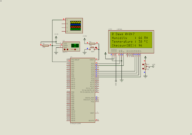
In this programming example, I will use PORTC of the STM32F103R6 to interface with the HD44780 LCD module. Where,

  • PC0 connects to LCD Register Select (RS)
  • LCD Read/Write (R/W) connects to GND as we only need to write data or command to the LCD module
  • PC1 connects to LCD Enable (E) pin. It latches data into the LCD module whenever a High to Low transition occurs.
  • PC4...PC7 connect to LCD data bus D4...D7.

Anyway the programmer should select other port or pin number of this micro-controller.

STM32F103R6 Interfaces To Character LCD In 4-Bit Mode
Device Configuration Tool
 

Device Configuration Tool could generates the source code for target controller without writing code.

  1. /* USER CODE BEGIN Header */
  2. /**
  3.   ******************************************************************************
  4.   * @file : main.c
  5.   * @brief : Main program body
  6.   ******************************************************************************
  7.   * @attention
  8.   *
  9.   * <h2><center>&copy; Copyright (c) 2023 STMicroelectronics.
  10.   * All rights reserved.</center></h2>
  11.   *
  12.   * This software component is licensed by ST under BSD 3-Clause license,
  13.   * the "License"; You may not use this file except in compliance with the
  14.   * License. You may obtain a copy of the License at:
  15.   * opensource.org/licenses/BSD-3-Clause
  16.   *
  17.   ******************************************************************************
  18.   */
  19. /* USER CODE END Header */
  20. /* Includes ------------------------------------------------------------------*/
  21. #include "main.h"
  22.  
  23. #define DPORT GPIOC->ODR
  24.  
  25. void delay1(uint16_t dTime){
  26. for(uint16_t i=0;i<dTime;i++);
  27. }
  28.  
  29. void delay2(uint8_t dTime){
  30. for(uint8_t i=0;i<dTime;i++) delay1(5000);
  31. }
  32.  
  33. void lcdCmd(uint8_t cmd){
  34. uint8_t temp=0x02;
  35. DPORT=temp|(cmd&0xF0);
  36. delay1(10);
  37. temp=0;
  38. DPORT=temp|(cmd&0xF0);
  39. delay1(100);
  40.  
  41. temp=0x02;
  42. DPORT=temp|(cmd<<4);
  43. delay1(10);
  44. temp=0;
  45. DPORT=temp|(cmd<<4);
  46. }
  47.  
  48. void lcdDat(uint8_t dat){
  49. uint8_t temp=0x03;
  50. DPORT=temp|(dat&0xF0);
  51. delay1(10);
  52. temp=0x01;
  53. DPORT=temp|(dat&0xF0);
  54. delay1(100);
  55.  
  56. temp=0x03;
  57. DPORT=temp|(dat<<4);
  58. delay1(10);
  59. temp=0x01;
  60. DPORT=temp|(dat<<4);
  61. }
  62.  
  63. void lcdInit(void){
  64. DPORT=0x00;
  65. delay1(2000);
  66. lcdCmd(0x33);
  67. delay1(100);
  68. lcdCmd(0x32);
  69. delay1(100);
  70. lcdCmd(0x28);
  71. delay1(100);
  72. lcdCmd(0x0F);
  73. delay1(100);
  74. lcdCmd(0x01);
  75. delay1(2000);
  76. lcdCmd(0x06);
  77. delay1(100);
  78. }
  79.  
  80. void lcdStr(uint8_t *str){
  81. while(*str) lcdDat(*str++);
  82. }
  83.  
  84. void lcdXY(uint8_t x,uint8_t y){
  85. // 20x4 LCD
  86. uint8_t tbe[]={0x80,0xC0,0x94,0xD4};
  87. lcdCmd(tbe[y-1]+x-1);
  88. delay1(100);
  89. }
  90.  
  91. void lcdClear(void){
  92. lcdCmd(0x01);
  93. delay1(100);
  94. }
  95.  
  96. /* Private function prototypes -----------------------------------------------*/
  97. void SystemClock_Config(void);
  98. static void MX_GPIO_Init(void);
  99.  
  100. /**
  101.   * @brief The application entry point.
  102.   * @retval int
  103.   */
  104. int main(void)
  105. {
  106. /* Reset of all peripherals, Initializes the Flash interface and the Systick. */
  107. HAL_Init();
  108.  
  109. /* Configure the system clock */
  110. SystemClock_Config();
  111.  
  112. /* Initialize all configured peripherals */
  113. MX_GPIO_Init();
  114.  
  115. lcdInit();
  116. lcdClear();
  117. delay2(200);
  118.  
  119. lcdXY(5,1);
  120. lcdStr("Hello World!");
  121. delay2(100);
  122.  
  123. lcdXY(1,2);
  124. lcdStr("STM32F103R6Tx ARM");
  125. delay2(100);
  126.  
  127. lcdXY(1,3);
  128. lcdStr("Cortex-M3 Processor");
  129. delay2(200);
  130.  
  131. lcdXY(5,4);
  132. lcdStr("STM32CubeIDE");
  133. delay2(200);
  134.  
  135. /* Infinite loop */
  136. /* USER CODE BEGIN WHILE */
  137. while (1)
  138. {
  139.  
  140. }
  141. }
  142.  
  143. /**
  144.   * @brief System Clock Configuration
  145.   * @retval None
  146.   */
  147. void SystemClock_Config(void)
  148. {
  149. RCC_OscInitTypeDef RCC_OscInitStruct = {0};
  150. RCC_ClkInitTypeDef RCC_ClkInitStruct = {0};
  151.  
  152. /** Initializes the RCC Oscillators according to the specified parameters
  153.   * in the RCC_OscInitTypeDef structure.
  154.   */
  155. RCC_OscInitStruct.OscillatorType = RCC_OSCILLATORTYPE_HSI;
  156. RCC_OscInitStruct.HSIState = RCC_HSI_ON;
  157. RCC_OscInitStruct.HSICalibrationValue = RCC_HSICALIBRATION_DEFAULT;
  158. RCC_OscInitStruct.PLL.PLLState = RCC_PLL_NONE;
  159. if (HAL_RCC_OscConfig(&RCC_OscInitStruct) != HAL_OK)
  160. {
  161. Error_Handler();
  162. }
  163. /** Initializes the CPU, AHB and APB buses clocks
  164.   */
  165. RCC_ClkInitStruct.ClockType = RCC_CLOCKTYPE_HCLK|RCC_CLOCKTYPE_SYSCLK
  166. |RCC_CLOCKTYPE_PCLK1|RCC_CLOCKTYPE_PCLK2;
  167. RCC_ClkInitStruct.SYSCLKSource = RCC_SYSCLKSOURCE_HSI;
  168. RCC_ClkInitStruct.AHBCLKDivider = RCC_SYSCLK_DIV1;
  169. RCC_ClkInitStruct.APB1CLKDivider = RCC_HCLK_DIV1;
  170. RCC_ClkInitStruct.APB2CLKDivider = RCC_HCLK_DIV1;
  171.  
  172. if (HAL_RCC_ClockConfig(&RCC_ClkInitStruct, FLASH_LATENCY_0) != HAL_OK)
  173. {
  174. Error_Handler();
  175. }
  176. }
  177.  
  178. /**
  179.   * @brief GPIO Initialization Function
  180.   * @param None
  181.   * @retval None
  182.   */
  183. static void MX_GPIO_Init(void)
  184. {
  185. GPIO_InitTypeDef GPIO_InitStruct = {0};
  186.  
  187. /* GPIO Ports Clock Enable */
  188. __HAL_RCC_GPIOC_CLK_ENABLE();
  189.  
  190. /*Configure GPIO pin Output Level */
  191. HAL_GPIO_WritePin(GPIOC, GPIO_PIN_0|GPIO_PIN_1|GPIO_PIN_4|GPIO_PIN_5
  192. |GPIO_PIN_6|GPIO_PIN_7, GPIO_PIN_RESET);
  193.  
  194. /*Configure GPIO pins : PC0 PC1 PC4 PC5
  195.   PC6 PC7 */
  196. GPIO_InitStruct.Pin = GPIO_PIN_0|GPIO_PIN_1|GPIO_PIN_4|GPIO_PIN_5
  197. |GPIO_PIN_6|GPIO_PIN_7;
  198. GPIO_InitStruct.Mode = GPIO_MODE_OUTPUT_PP;
  199. GPIO_InitStruct.Pull = GPIO_NOPULL;
  200. GPIO_InitStruct.Speed = GPIO_SPEED_FREQ_LOW;
  201. HAL_GPIO_Init(GPIOC, &GPIO_InitStruct);
  202.  
  203. }
  204.  
  205. /* USER CODE BEGIN 4 */
  206.  
  207. /* USER CODE END 4 */
  208.  
  209. /**
  210.   * @brief This function is executed in case of error occurrence.
  211.   * @retval None
  212.   */
  213. void Error_Handler(void)
  214. {
  215. /* USER CODE BEGIN Error_Handler_Debug */
  216. /* User can add his own implementation to report the HAL error return state */
  217. __disable_irq();
  218. while (1)
  219. {
  220. }
  221. /* USER CODE END Error_Handler_Debug */
  222. }
  223.  
  224. #ifdef USE_FULL_ASSERT
  225. /**
  226.   * @brief Reports the name of the source file and the source line number
  227.   * where the assert_param error has occurred.
  228.   * @param file: pointer to the source file name
  229.   * @param line: assert_param error line source number
  230.   * @retval None
  231.   */
  232. void assert_failed(uint8_t *file, uint32_t line)
  233. {
  234. /* USER CODE BEGIN 6 */
  235. /* User can add his own implementation to report the file name and line number,
  236.   ex: printf("Wrong parameters value: file %s on line %d\r\n", file, line) */
  237. /* USER CODE END 6 */
  238. }
  239. #endif /* USE_FULL_ASSERT */
  240.  
  241. /************************ (C) COPYRIGHT STMicroelectronics *****END OF FILE****/
  242.   

I use a 20x4 character LCD. If you prefer a 16x2 LCD you need to modify its display RAM address in the program. Click here to download its source file.

Tuesday, September 8, 2020

STM32F103R6 Two-Digit 7-Segments Display Using SN74HC595N Shift Registers

In this programming example, I will use the high speed SPI module of the STM32F103R6 to interface with shift registers chips. The Serial Peripheral Interface (SPI) is a microprocessor high speed communication protocol using three wires. It has at least serial clock, serial data, and latch pins. It's asynchronous type. This communication protocol commonly used with shift registers chip, serial Flash memory chip, serial SRAM, serial EEPROM, etc.

STM32F103R6 Two-Digit 7-Segments Display Using SN74HC595N Shift Registers
Simulating Program

A serial-in-parallel-out shift registers is popular for expanding the number of digital output pins. We can find two popular types - the SN74HC164 and the SN74HC595N. These chips can be use to drive LEDs, 7-Segment display, dot matrix display, etc.

STM32F103R6 Two-Digit 7-Segments Display Using SN74HC595N Shift Registers
The SN74HC595N In DIP Package

STM32F103R6 Two-Digit 7-Segments Display Using SN74HC595N Shift Registers
The SN74HC595N Pins Diagram


For a single register we use an 8-bit transfer mode. However if we use more than one register as it's shown in this programming tutorial, we can also use the 8-bit transfer mode. But for convenience we must use the 16-bit transfer mode. The hardware NSS signal is activated once for 16-bit transfer mode. However we can use software latch pin instead.

STM32F103R6 Two-Digit 7-Segments Display Using SN74HC595N Shift Registers
Device Configuration Tool

A Push button connects to PC0. Whenever it's press, the counter value will increase. It will roll down to 0 when it reaches 100. The 7-Segment display is common cathode type.

  1. /* USER CODE BEGIN Header */
  2. /**
  3.   ******************************************************************************
  4.   * @file : main.c
  5.   * @brief : Main program body
  6.   ******************************************************************************
  7.   * @attention
  8.   *
  9.   * <h2><center>&copy; Copyright (c) 2022 STMicroelectronics.
  10.   * All rights reserved.</center></h2>
  11.   *
  12.   * This software component is licensed by ST under BSD 3-Clause license,
  13.   * the "License"; You may not use this file except in compliance with the
  14.   * License. You may obtain a copy of the License at:
  15.   * opensource.org/licenses/BSD-3-Clause
  16.   *
  17.   ******************************************************************************
  18.   */
  19. /* USER CODE END Header */
  20. /* Includes ------------------------------------------------------------------*/
  21. #include "main.h"
  22.  
  23. /* Private variables ---------------------------------------------------------*/
  24. SPI_HandleTypeDef hspi1;
  25.  
  26. /* Private function prototypes -----------------------------------------------*/
  27. void SystemClock_Config(void);
  28. static void MX_GPIO_Init(void);
  29. static void MX_SPI1_Init(void);
  30.  
  31. /**
  32.   * @brief The application entry point.
  33.   * @retval int
  34.   */
  35.  
  36. #define SW_Press (HAL_GPIO_ReadPin(SW_GPIO_Port,SW_Pin))==GPIO_PIN_RESET
  37.  
  38. const uint8_t Cdata[10]={0x3F,0x06,0x5B,0x4F,0x66,0x6D,0x7D,0x07,0x7F,0x6F};
  39.  
  40. int main(void)
  41. {
  42. uint8_t newCount=0,oldCount=100;
  43. uint8_t myData[2]={};
  44. myData[0]=Cdata[5];
  45. myData[1]=Cdata[1];
  46. /* Reset of all peripherals, Initializes the Flash interface and the Systick. */
  47. HAL_Init();
  48.  
  49. /* Configure the system clock */
  50. SystemClock_Config();
  51.  
  52. /* Initialize all configured peripherals */
  53. MX_GPIO_Init();
  54. MX_SPI1_Init();
  55.  
  56. /* Infinite loop */
  57. /* USER CODE BEGIN WHILE */
  58. while (1)
  59. {
  60. if(SW_Press){
  61. while(SW_Press);
  62. newCount++;
  63. }
  64. if(newCount>99) newCount=0;
  65. if(newCount!=oldCount){
  66. myData[0]=Cdata[newCount%10];
  67. myData[1]=Cdata[newCount/10];
  68. //HAL_SPI_Transmit(&hspi1,&myData,sizeof(myData),100);
  69. HAL_SPI_Transmit(&hspi1,&myData,1,100);
  70. oldCount=newCount;
  71. }
  72. }
  73. }
  74.  
  75. /**
  76.   * @brief System Clock Configuration
  77.   * @retval None
  78.   */
  79. void SystemClock_Config(void)
  80. {
  81. RCC_OscInitTypeDef RCC_OscInitStruct = {0};
  82. RCC_ClkInitTypeDef RCC_ClkInitStruct = {0};
  83.  
  84. /** Initializes the RCC Oscillators according to the specified parameters
  85.   * in the RCC_OscInitTypeDef structure.
  86.   */
  87. RCC_OscInitStruct.OscillatorType = RCC_OSCILLATORTYPE_HSI;
  88. RCC_OscInitStruct.HSIState = RCC_HSI_ON;
  89. RCC_OscInitStruct.HSICalibrationValue = RCC_HSICALIBRATION_DEFAULT;
  90. RCC_OscInitStruct.PLL.PLLState = RCC_PLL_NONE;
  91. if (HAL_RCC_OscConfig(&RCC_OscInitStruct) != HAL_OK)
  92. {
  93. Error_Handler();
  94. }
  95. /** Initializes the CPU, AHB and APB buses clocks
  96.   */
  97. RCC_ClkInitStruct.ClockType = RCC_CLOCKTYPE_HCLK|RCC_CLOCKTYPE_SYSCLK
  98. |RCC_CLOCKTYPE_PCLK1|RCC_CLOCKTYPE_PCLK2;
  99. RCC_ClkInitStruct.SYSCLKSource = RCC_SYSCLKSOURCE_HSI;
  100. RCC_ClkInitStruct.AHBCLKDivider = RCC_SYSCLK_DIV1;
  101. RCC_ClkInitStruct.APB1CLKDivider = RCC_HCLK_DIV1;
  102. RCC_ClkInitStruct.APB2CLKDivider = RCC_HCLK_DIV1;
  103.  
  104. if (HAL_RCC_ClockConfig(&RCC_ClkInitStruct, FLASH_LATENCY_0) != HAL_OK)
  105. {
  106. Error_Handler();
  107. }
  108. }
  109.  
  110. /**
  111.   * @brief SPI1 Initialization Function
  112.   * @param None
  113.   * @retval None
  114.   */
  115. static void MX_SPI1_Init(void)
  116. {
  117.  
  118. /* USER CODE BEGIN SPI1_Init 0 */
  119.  
  120. /* USER CODE END SPI1_Init 0 */
  121.  
  122. /* USER CODE BEGIN SPI1_Init 1 */
  123.  
  124. /* USER CODE END SPI1_Init 1 */
  125. /* SPI1 parameter configuration*/
  126. hspi1.Instance = SPI1;
  127. hspi1.Init.Mode = SPI_MODE_MASTER;
  128. hspi1.Init.Direction = SPI_DIRECTION_2LINES;
  129. hspi1.Init.DataSize = SPI_DATASIZE_16BIT;
  130. hspi1.Init.CLKPolarity = SPI_POLARITY_LOW;
  131. hspi1.Init.CLKPhase = SPI_PHASE_1EDGE;
  132. hspi1.Init.NSS = SPI_NSS_HARD_OUTPUT;
  133. hspi1.Init.BaudRatePrescaler = SPI_BAUDRATEPRESCALER_128;
  134. hspi1.Init.FirstBit = SPI_FIRSTBIT_MSB;
  135. hspi1.Init.TIMode = SPI_TIMODE_DISABLE;
  136. hspi1.Init.CRCCalculation = SPI_CRCCALCULATION_DISABLE;
  137. hspi1.Init.CRCPolynomial = 10;
  138. if (HAL_SPI_Init(&hspi1) != HAL_OK)
  139. {
  140. Error_Handler();
  141. }
  142. /* USER CODE BEGIN SPI1_Init 2 */
  143.  
  144. /* USER CODE END SPI1_Init 2 */
  145.  
  146. }
  147.  
  148. /**
  149.   * @brief GPIO Initialization Function
  150.   * @param None
  151.   * @retval None
  152.   */
  153. static void MX_GPIO_Init(void)
  154. {
  155. GPIO_InitTypeDef GPIO_InitStruct = {0};
  156.  
  157. /* GPIO Ports Clock Enable */
  158. __HAL_RCC_GPIOC_CLK_ENABLE();
  159. __HAL_RCC_GPIOA_CLK_ENABLE();
  160.  
  161. /*Configure GPIO pin : SW_Pin */
  162. GPIO_InitStruct.Pin = SW_Pin;
  163. GPIO_InitStruct.Mode = GPIO_MODE_INPUT;
  164. GPIO_InitStruct.Pull = GPIO_PULLUP;
  165. HAL_GPIO_Init(SW_GPIO_Port, &GPIO_InitStruct);
  166.  
  167. }
  168.  
  169. /* USER CODE BEGIN 4 */
  170.  
  171. /* USER CODE END 4 */
  172.  
  173. /**
  174.   * @brief This function is executed in case of error occurrence.
  175.   * @retval None
  176.   */
  177. void Error_Handler(void)
  178. {
  179. /* USER CODE BEGIN Error_Handler_Debug */
  180. /* User can add his own implementation to report the HAL error return state */
  181. __disable_irq();
  182. while (1)
  183. {
  184. }
  185. /* USER CODE END Error_Handler_Debug */
  186. }
  187.  
  188. #ifdef USE_FULL_ASSERT
  189. /**
  190.   * @brief Reports the name of the source file and the source line number
  191.   * where the assert_param error has occurred.
  192.   * @param file: pointer to the source file name
  193.   * @param line: assert_param error line source number
  194.   * @retval None
  195.   */
  196. void assert_failed(uint8_t *file, uint32_t line)
  197. {
  198. /* USER CODE BEGIN 6 */
  199. /* User can add his own implementation to report the file name and line number,
  200.   ex: printf("Wrong parameters value: file %s on line %d\r\n", file, line) */
  201. /* USER CODE END 6 */
  202. }
  203. #endif /* USE_FULL_ASSERT */
  204.  
  205. /************************ (C) COPYRIGHT STMicroelectronics *****END OF FILE****/
  206.  

Click here to download its source file.

STM32F103R6 Two-Digit 7-Segments Display Using SN74HC595N Shift Registers
SPI Send In 16-bit Mode