Showing posts with label AVR. Show all posts

Sunday, August 23, 2020

Using ATMega32 Internal EEPROM Memory

Overview

Beside program memory and data memory, the ATMega32 contains up to 1024 bytes of internal EEPROM for auxiliary storage. It can handle up to 100,000 Write/Erase cycles. However its access time is slower than SRAM. Each registers of EEPROM are 8-bit wide unlike the internal program memory that is 16-bit wide. Program memory space is quite larger than EEPROM memory space. In the case of the ATMega32 the program memory is 32K bytes.

It's important to store user's settings data in to this non-volatile memory to prevent data lost next time the MCU turns on, or power interruption. We can also store this type of data in internal program memory (Flash Memory).

Writing And Reading EEPROM Example

The AVR LibC contains the "eeprom.h" library allow us to read and write different kind of data types inside EEPROM such as byte, word, float, etc. Even it's 8-bit wide the library handle this task for the programmers. This library has the following routines,

  • eeprom_read_byte
  • eeprom_read_word
  • eeprom_read_dword
  • eeprom_read_float
  • eeprom_read_block


  • eeprom_write_byte
  • eeprom_write_word
  • eeprom_write_dword
  • eeprom_write_float
  • eeprom_write_block

and other update routine. For more detail you can see the header file.

For an introductory example, the program will write a set of data of 256 addresses, and read them back.

Using ATMega32 Internal EEPROM Memory
Writing and Reading EEPROM Example
I use AVR LibC in Microchip Studio.

  1. /*
  2.  * EepromEx1.c
  3.  *
  4.  * Created: 7/20/2023 6:53:22 PM
  5.  * Author : Admin
  6.  */
  7.  
  8. #include <avr/io.h>
  9.  
  10. #include <avr/eeprom.h>
  11.  
  12. #define F_CPU 8000000UL
  13. #include <util/delay.h>
  14.  
  15.  
  16. int main(void)
  17. {
  18. DDRC = 0xFF;
  19. for (uint8_t i= 0;i<0xFF;i++)
  20. eeprom_write_byte(i,i);
  21. while (1)
  22. {
  23. for (uint8_t i = 0; i<0xFF; i++)
  24. {
  25. PORTC = eeprom_read_byte(i);
  26. _delay_ms(250);
  27. }
  28.  
  29. }
  30. }
  31.  
  32.  

Click here to download its zip file.

Using the EEMEM attribute

EEMEM attribute allow us to declare data on EEPROM space. We can read or write the data using its address. In the following example, I declare a data array on EEPROM first, and then I read those data back.

  1. /*
  2.  * EepromEx2.c
  3.  *
  4.  * Created: 7/20/2023 9:16:24 PM
  5.  * Author : Admin
  6.  */
  7.  
  8. #include <avr/io.h>
  9.  
  10. #define F_CPU 8000000UL
  11. #include <util/delay.h>
  12.  
  13. #include <avr/eeprom.h>
  14.  
  15. const uint8_t myData[] EEMEM = {0x01,0x02,0x04,0x08,0x10,0x20,0x40,0x80};
  16.  
  17. int main(void)
  18. {
  19. DDRC=0xFF;
  20. while (1)
  21. {
  22. for (int i =0;i<sizeof(myData);i++)
  23. {
  24. char temp = &myData[i];
  25. PORTC=eeprom_read_byte(temp);
  26. _delay_ms(1000);
  27. }
  28.  
  29. }
  30. }
  31.  
  32.  

Schematic Diagram

Using ATMega32 Internal EEPROM Memory
Using the EEMEM attribute
 

Click here to download its zip file.

Here's another example. I store constant 7-Segment data in EEPROM. The program will read them back and show it on display.

  1. /*
  2.  * EepromEx3.c
  3.  *
  4.  * Created: 7/20/2023 10:17:26 PM
  5.  * Author : Admin
  6.  */
  7.  
  8. #include <avr/io.h>
  9. #include <avr/eeprom.h>
  10.  
  11. #define F_CPU 8000000UL
  12. #include <util/delay.h>
  13.  
  14. /*Declare EEPROM Storage*/
  15. const uint8_t cCathode[] EEMEM = {0x3F,0x06,0x5B,0x4F,0x66,0x6D,0x7D,0x07,
  16. 0x7F,0x6F,0x77,0x7C,0x39,0x5E,0x79,0x71};
  17. const uint8_t cAnode[] EEMEM = {0xC0,0xF9,0xA4,0xB0,0x99,0x92,0x82,0xF8,0x80,
  18. 0x90,0x88,0x83,0xC6,0xA1,
  19. 0x86,0x8E};
  20.  
  21. int main(void)
  22. {
  23. DDRC=0xFF;
  24. DDRD=0xFF;
  25. while (1)
  26. {
  27. for (int i=0;i<sizeof(cCathode);i++)
  28. {
  29. PORTD=eeprom_read_byte(&cCathode[i]);
  30. PORTC=eeprom_read_byte(&cAnode[i]);
  31. _delay_ms(500);
  32. }
  33. }
  34. }
  35.  
  36.  


Using ATMega32 Internal EEPROM Memory
Displaying 7-Segment Data From EEPROM

 Click here to download its zip file.

Reading/Writing With Switches and a 7-Segment Display

In this example I use two DIP switches, one for input address while another one for input data that will write data into EEPROM. Input data is between 0 and 0x0F.

Using ATMega32 Internal EEPROM Memory
Reading/Writing With Switches and a 7-Segment Display
One the SW2 push button is pressed, it will write data from input DSW2 DIP switch with a given address from DSW1 DIP switch.

With any input address change from DSW1, it will read the data from new given address.

  1. /*
  2.  * EepromEx4.c
  3.  *
  4.  * Created: 7/21/2023 9:21:18 AM
  5.  * Author : Admin
  6.  */
  7.  
  8. #include <avr/io.h>
  9.  
  10. #define F_CPU 8000000UL
  11. #include <util/delay.h>
  12.  
  13. #include <avr/eeprom.h>
  14.  
  15. #define Write (PIND&0x08)==0
  16. #define LED 7
  17.  
  18. /*Declare EEPROM Storage*/
  19. uint8_t Edata[256] EEMEM;
  20.  
  21. const uint8_t cAnode[] = {0xC0,0xF9,0xA4,0xB0,0x99,0x92,0x82,0xF8,
  22. 0x80,0x90,0x88,0x83,0xC6,0xA1,0x86,0x8E};
  23.  
  24. int main(void)
  25. {
  26. uint8_t oldAddr=1,newAddr=0,segment=0,inputData;
  27. DDRA=0x00;
  28. PINA=0xFF;
  29. DDRC=0xFF;
  30. PORTC=0xFF;
  31. DDRD=0x07;
  32. PORTD=0xF8;
  33. while (1)
  34. {
  35. /*Check Address Change*/
  36. if (newAddr!=oldAddr)
  37. {
  38. segment = eeprom_read_byte(&Edata[newAddr]);
  39. oldAddr = newAddr;
  40. }
  41. PORTC = cAnode[segment];
  42. newAddr = PINA;
  43. if (Write)
  44. {
  45. PORTC&=~(1<<LED);
  46. inputData = (PIND&0xF0)>>4;
  47. eeprom_write_byte(&Edata[newAddr],inputData);
  48. while(Write);
  49. segment = eeprom_read_byte(&Edata[newAddr]);
  50. PORTC|=(1<<LED);
  51. }
  52. }
  53. }
  54.  
  55.  

Click here to download source file. 

The example above use the 7-Segment data that store in SRAM. We can also store and read it from EEPROM.

  1. /*
  2.  * EepromEx5.c
  3.  *
  4.  * Created: 7/21/2023 3:11:48 PM
  5.  * Author : Admin
  6.  */
  7.  
  8. #include <avr/io.h>
  9.  
  10. #define F_CPU 8000000UL
  11. #include <util/delay.h>
  12.  
  13. #include <avr/eeprom.h>
  14.  
  15. #define Write (PIND&0x08)==0
  16. #define LED 7
  17.  
  18. /*Declare EEPROM Storage*/
  19. uint8_t Edata[256] EEMEM;
  20.  
  21. uint8_t cAnode[] EEMEM = {0xC0,0xF9,0xA4,0xB0,0x99,0x92,0x82,0xF8,
  22. 0x80,0x90,0x88,0x83,0xC6,0xA1,0x86,0x8E};
  23.  
  24. int main(void)
  25. {
  26. uint8_t oldAddr=1,newAddr=0,segment=0,inputData,DisplayData=0;
  27. DDRA=0x00;
  28. PINA=0xFF;
  29. DDRC=0xFF;
  30. PORTC=0xFF;
  31. DDRD=0x07;
  32. PORTD=0xF8;
  33. while (1)
  34. {
  35. /*Check Address Change*/
  36. if (newAddr!=oldAddr)
  37. {
  38. segment = eeprom_read_byte(&Edata[newAddr]);
  39. DisplayData = eeprom_read_byte(&cAnode[segment]);
  40. oldAddr = newAddr;
  41. }
  42. PORTC = DisplayData;
  43. newAddr = PINA;
  44. if (Write)
  45. {
  46. PORTC&=~(1<<LED);
  47. inputData = (PIND&0xF0)>>4;
  48. eeprom_write_byte(&Edata[newAddr],inputData);
  49. while(Write);
  50. segment = eeprom_read_byte(&Edata[newAddr]);
  51. DisplayData = eeprom_read_byte(&cAnode[segment]);
  52. PORTC|=(1<<LED);
  53. }
  54. }
  55. }
  56.  
  57.  
  58.  

Click here to download its source file.

Storing and Reading Data From Flash Memory of ATMega32

ATMega32 contains 32K bytes of internal Flash memory for program storage. The Flash is organized as 16K x 16 because all AVR instructions are 16 or 32 bits wide. For software security, the Flash Program memory space is divided into two sections, Boot Program section and Application Program section.

The Flash Memory has an endurance of at least 10,000 write/erase cycles. The ATMega32 Program Counter (PC) is 14-bit wide, thus addressing the 16K program memory locations. 

ATMega32 has 2K bytes of internal SRAM. It's far smaller than its internal Flash. For any situation that the user needs to store a large amount of constant data, it is effective to store and read those data from internal Flash. For example we need to store font data at the amount of 1K bytes. This example project uses a lot of internal SRAM since the program store font and graphic data in SRAM instead of Flash.

The AVR LibC "pgmspace.h" contains routine that declare data into Flash Memory, reading byte data from Flash Memory, etc.

Storing and Reading Data From Flash Memory of ATMega32
Program Simulation
In this example, we store 7-Segments display data in Flash memory. At run-time the program will read 7-Segment data from internal Flash. It will display on a single 7-Segment display connects to PORTC.

  1. /*
  2.  * Example_2.c
  3.  *
  4.  * Created: 7/19/2023 1:52:49 PM
  5.  * Author : Admin
  6.  */
  7.  
  8. #include <avr/io.h>
  9. #include <avr/pgmspace.h>
  10. #define F_CPU 8000000UL
  11. #include "util/delay.h"
  12.  
  13. /*Declare constant data that will store in program Flash Memory*/
  14. const char cCathode[] PROGMEM =
  15. {0x3F,0x06,0x5B,0x4F,0x66,0x6D,0x7D,0x07,0x7F,0x6F,0x77,0x7C,0x39,0x5E,0x79,0x71};
  16. const char cAnode[] PROGMEM =
  17. {0xC0,0xF9,0xA4,0xB0,0x99,0x92,0x82,0xF8,0x80,0x90,0x88,0x83,0xC6,0xA1,0x86,0x8E};
  18.  
  19. int main(void)
  20. {
  21. DDRC = 0xFF;
  22. while (1)
  23. {
  24. for (char i=0;i<16;i++)
  25. {
  26. /*Read Flash Data and assign to PORTC*/
  27. PORTC = pgm_read_byte(&cCathode[i]);
  28. _delay_ms(500);
  29. }
  30. }
  31. }
  32.  
  33.  


Click here to download its zip file.

ATMega32 Simple Graphical LCD Interfacing Using A 128x64 GLCD

Overview

A graphical LCD can show variety of data including texts, image, symbols, graphic, etc. It usually has an LCD controller inside. A popular LCD controller was KS0108 manufactured by Samsung Electronics. Currently there are many equivalent controller chips. This controller chip was release a few decade ago but it still in use in some small embedded controller projects.

ATMega32 Simple Graphical LCD Interfacing Using A 128x64 GLCD
Sample Program

An example of using this LCD controller chip is a small 128x64 GLCD module. It use a parallel port interface with a few control lines. However some newer equivalent controller chips have an I2C and SPI interface, reducing the number of I/O pins that interface between the LCD and the microprocessor.

Using this type of graphical LCD is very straight forward. Most of electronic hobbyists use Arduino because it's open source, and there are a lot of libraries. CCS PICC compiler for PIC micro-controller also has a library to controller this GLCD. Mikroelectronika have many compilers targeting different type of micro-controllers including PIC, AVR, 8051, ARM, etc. It has many libraries for LCD and graphical LCD including this type. However either CCS PICC and Mikroelectronika's compilers, the user needs to pay for license to get non-restricted access to their compilers.

Microchip Studio (formerly Atmel Studio) is a free IDE from Microchip Technology. We can write the program for Microchip AVR or ARM micro-controller without restriction. For AVR type we can use AVR LIBC that's an open source tool chain. 

RT12864J-1 128x64 Graphical LCD

I bought this GLCD module from Ebay many years ago. At that time it was expensive. However it's a low cost now.


ATMega32 Simple Graphical LCD Interfacing Using A 128x64 GLCD
Front Panel

ATMega32 Simple Graphical LCD Interfacing Using A 128x64 GLCD
Back Panel

Inside this LCD module there are two KS0108 display driver chip, and one KS0107 common driver chip. Since they are chip-on-board we can not see these chips.

ATMega32 Simple Graphical LCD Interfacing Using A 128x64 GLCD
RT12864J-1 Datasheet
This module works at +5VDC. It uses the 6800 parallel interface. Command and data are latched into the controller chip at positive transition of Enabel pin (E) between CSA and CSB selection. 

Chip Select A (CSA) and Chip Select B (CSB) are active high. we can select one of them, or both. 

Data/Instruction (DI) or RS (Register Select pin) is use for choosing between data or instruction code. Data refers to any graphic displaying on screen.

Read or Write (R/W) pin is use for reading or writing data/instruction to LCD controller. We just need to write data to controller. So we must connect it to ground.

Reset (RST) pin is active low signal that will restart the module. We will need to connect it to VCC via a current cutting resistor allowing this module to operate.

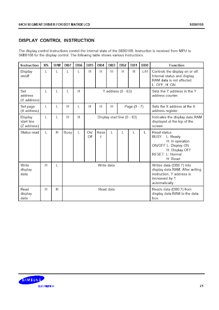
Command and sending this LCD is very simple, as it's shown in device data sheet.

ATMega32 Simple Graphical LCD Interfacing Using A 128x64 GLCD

ATMega32 Simple Graphical LCD Interfacing Using A 128x64 GLCD

ATMega32 Simple Graphical LCD Interfacing Using A 128x64 GLCD
The origin of data on screen starts from the upper left corner. 

Hardware Interfacing and Programming

I draw and simulate this example program using Proteus 8. This software can simulate the circuit. However the footprint for RT12864J-1 Graphical LCD doesn't exist in this simulator.


ATMega32 Simple Graphical LCD Interfacing Using A 128x64 GLCD
Schematic Diagram

I use Microchip Studio IDE to write C codes for this program.

  1. /*
  2.  * RT12864Test4.c
  3.  *
  4.  * Created: 7/15/2023 11:57:20 AM
  5.  * Author : Admin
  6.  */
  7.  
  8. #include <avr/io.h>
  9. #include "font5x8.h"
  10. #include "diy-logo.h"
  11.  
  12. #define F_CPU 8000000UL
  13. #include <util/delay.h>
  14.  
  15. #define LCD_DATA PORTC
  16. #define LCD_CONT PORTD
  17.  
  18. #define LCD_EN 0
  19. #define LCD_DI 1
  20. #define LCD_CS1 2
  21. #define LCD_CS2 3
  22. #define LCD_RST 4
  23.  
  24. unsigned char dotCount=0;
  25.  
  26. void lcdCommand(unsigned char cmd,char cs){
  27. if(cs==1) LCD_CONT|=(1<<LCD_CS1);
  28. else if(cs==2) LCD_CONT|=(1<<LCD_CS2);
  29. LCD_CONT&=~(1<<LCD_DI);
  30. LCD_CONT|=(1<<LCD_EN);
  31. LCD_DATA=cmd;
  32. LCD_CONT&=~(1<<LCD_EN);
  33. _delay_us(10);
  34. if(cs==1) LCD_CONT&=~(1<<LCD_CS1);
  35. else if(cs==2) LCD_CONT&=~(1<<LCD_CS2);
  36. }
  37.  
  38. void lcdData(char data,char cs){
  39. if(cs==1) LCD_CONT|=(1<<LCD_CS1);
  40. else if(cs==2) LCD_CONT|=(1<<LCD_CS2);
  41. LCD_CONT|=(1<<LCD_DI);
  42. LCD_CONT|=(1<<LCD_EN);
  43. LCD_DATA=data;
  44. LCD_CONT&=~(1<<LCD_EN);
  45. _delay_us(10);
  46. if(cs==1) LCD_CONT&=~(1<<LCD_CS1);
  47. else if (cs==2) LCD_CONT&=~(1<<LCD_CS2);
  48. }
  49.  
  50. void lcdHorizontal(unsigned char horizontal){
  51. lcdCommand(0x40+horizontal,1);
  52. lcdCommand(0x40+horizontal,2);
  53.  
  54. }
  55.  
  56. void lcdVerticalLine(unsigned char line){
  57. lcdCommand(0xB8+line,1);
  58. lcdCommand(0xB8+line,2);
  59. dotCount=0;
  60. }
  61.  
  62. void lcdSetZ(unsigned char zAxis){
  63. lcdCommand(0xC0+zAxis,1);
  64. lcdCommand(0xC0+zAxis,2);
  65. }
  66.  
  67. void lcdXy(unsigned char x,unsigned char y){
  68. if(x<64){
  69. lcdCommand(0x40+x,1);
  70. lcdCommand(0x40+0,2);
  71. }
  72. else{
  73. lcdCommand(0x40+0,1);
  74. lcdCommand(0x40+x-63,2);
  75. }
  76.  
  77. lcdCommand(0xB8+y,1);
  78. lcdCommand(0xB8+y,2);
  79. dotCount=x;
  80. }
  81.  
  82. void writeChar(unsigned char aph){
  83. for (int i=0;i<5;i++)
  84. {
  85. if(dotCount<64) lcdData(font5x8[((aph-32)*5)+i],1);
  86. else lcdData(font5x8[((aph-32)*5)+i],2);
  87. dotCount++;
  88. }
  89. lcdData(0,(dotCount<64)?1:2);
  90. dotCount++;
  91. if (dotCount>127)
  92. {
  93. dotCount=0;
  94. }
  95. }
  96.  
  97. void writeCharDelay(unsigned char aph,unsigned int dT){
  98. for (int i=0;i<5;i++)
  99. {
  100. if(dotCount<64) lcdData(font5x8[((aph-32)*5)+i],1);
  101. else lcdData(font5x8[((aph-32)*5)+i],2);
  102. if(dT!=0) for(int i=0;i<dT;i++) _delay_us(1000);
  103. dotCount++;
  104. }
  105. lcdData(0,(dotCount<64)?1:2);
  106. dotCount++;
  107. if (dotCount>127)
  108. {
  109. dotCount=0;
  110. }
  111. }
  112.  
  113. void lcdString(char *str){
  114. while(*str)
  115. writeChar(*str++);
  116. }
  117.  
  118. void writeStringDelay(char *str,unsigned int dT){
  119. while(*str){
  120. if(dT!=0) writeCharDelay(*str++,dT);
  121. else writeChar(*str++);
  122. }
  123. }
  124.  
  125. void lcdInit(void){
  126. DDRC=0xFF;
  127. DDRD=0xFF;
  128. /*Display On*/
  129. lcdCommand(0x3F,1);
  130. lcdCommand(0x3F,2);
  131. dotCount = 0;
  132. }
  133.  
  134. void lcdClearScreen(){
  135.  
  136. for (int i=0;i<8;i++)
  137. {
  138. lcdXy(0,i);
  139. for(int j=0;j<128;j++){
  140. lcdData(0,1);
  141. lcdData(0,2);
  142. }
  143. }
  144. dotCount=0;
  145. lcdXy(0,0);
  146. }
  147.  
  148. void lcdClearSection(unsigned char x,unsigned char y,unsigned char dot){
  149. lcdXy(x,y);
  150. dotCount=x;
  151. for (int i=0;i<dot;i++)
  152. {
  153. if(dotCount<64) lcdData(0,1);
  154. else lcdData(0,2);
  155. dotCount++;
  156. }
  157.  
  158. if (dotCount>127)
  159. {
  160. dotCount=0;
  161. }
  162. }
  163.  
  164. void showGraphic(void){
  165. unsigned int kCount=0;
  166. for (int i=0;i<8;i++)
  167. {
  168.  
  169. dotCount=0;
  170. lcdXy(0,i);
  171. for (int j=kCount;j<kCount+128;j++)
  172. {
  173. if(dotCount<64) lcdData(logo[j],1);
  174. else lcdData(logo[j],2);
  175. dotCount++;
  176. }
  177. kCount+=128;
  178. }
  179. }
  180.  
  181. int main(void)
  182. {
  183. lcdInit();
  184. lcdClearScreen();
  185. while (1)
  186. {
  187. lcdXy(25,0);
  188. writeStringDelay("HELLO WORLD!",10);
  189. lcdXy(0,1);
  190. writeStringDelay("ATMEGA32 Graphic LCD ",10);
  191. lcdXy(0,2);
  192. writeStringDelay("Programming in C With",10);
  193. lcdXy(0,3);
  194. writeStringDelay("Microchip Studio",10);
  195. lcdXy(0,4);
  196. writeStringDelay("DIY-Instruments",10);
  197. lcdXy(0,5);
  198. writeStringDelay("KS0108 LCD Controller",10);
  199. lcdXy(0,6);
  200. writeStringDelay("RT12864J-1 128x64",10);
  201. lcdXy(0,7);
  202. writeStringDelay("Graphical LCD Module",10);
  203. _delay_ms(5000);
  204. lcdClearScreen();
  205.  
  206. lcdXy(0,0);
  207. showGraphic();
  208. _delay_ms(5000);
  209. lcdClearScreen();
  210. }
  211. }
  212.  


Click here to download its source file.

ATMega32 Simple Graphical LCD Interfacing Using A 128x64 GLCD
Hardware Testing 1

ATMega32 Simple Graphical LCD Interfacing Using A 128x64 GLCD

Hardware Testing 2

ATMega32 Simple Graphical LCD Interfacing Using A 128x64 GLCD
Atmega32 Test Board With PICKit2 ICSP

ATMega32 Simple Graphical LCD Interfacing Using A 128x64 GLCD
Atmega32 Test Board With PICKit2 ICSP