Shift Registers are very useful for expanding the controller I/O ports. However driving a dot matrix display, or multiple seven-segment display also need this kind of chip. Because only multiplexing could not achieve a good displaying task.
 |
| Eight-Digit and Ten-Digit Serial Seven-Segment Display Using SN74HC595N |
It's not important to make any DIY display like this. But I have many common-cathode type seven-segments display, SN74HC595N shift registers, copper clad board, etc. So I want to use them all rather than keep them new in my own repair shop.
The design was complicated due to multiple count of connection between register to register, and register to display. So I tried to eliminate some components especially the current cutting resistors.
The shift register chip output pin voltage is +5V while the display need around 2V to operate. Without using dozens of current cutting resistors, I reduce the voltage by making voltage division. I add 3 rectifier diodes in series with each common cathodes of the display to divide the voltage.
Eight-Digit Seven-Segment Display
For the first time I design, I was unwilling to do this task due to difficulty in PCB fabrication, and laser printing toner problem. Because the ink cartridge was old. So I only made an 8-digit display.
 |
| Arduino Test Program |
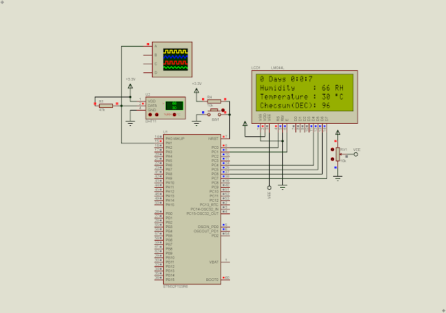
I use Proteus 8.10 to design the schematic and PCB.
 |
| Schematic Design |
|
PCB View In Proteus |

 | |
| Design 3D View |
 |
| Component Side Label Transferring |
 |
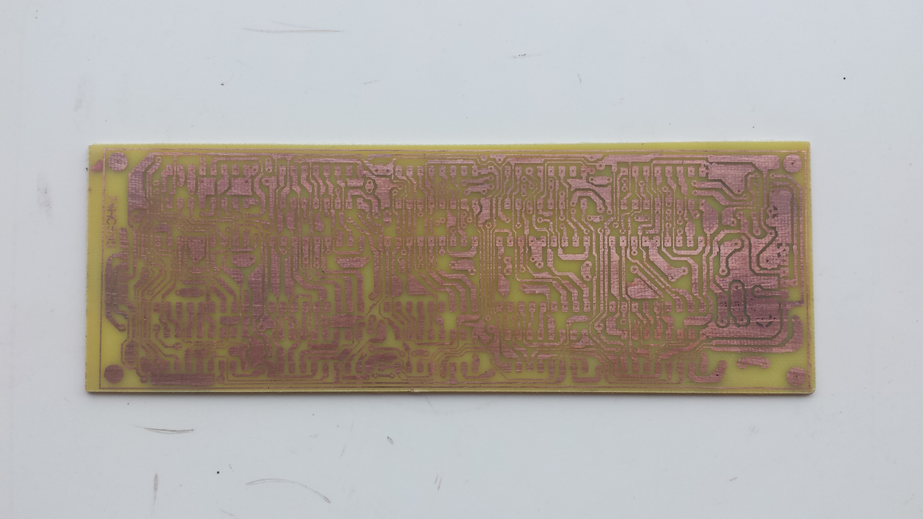
| Copper Side After Etching |
 |
| Copper Side After Soldering |
 |
| Copper Side Before Etching |
 |
| Finished PCBA Assembling |
It works well but the display doesn't have Dot Point.
 |
| I firstly test this PCBA With Arduino Program Due To Ease Of Use. |
I store this design file in Github.
Arduino Test Program #1 Using SPI
#include <SPI.h>
void setup() {
// put your setup code here, to run once:
SPI.begin();
pinMode(10,OUTPUT);
}
void loop() {
// put your main code here, to run repeatedly:
digitalWrite(10,LOW);
SPI.transfer(0x3F);
SPI.transfer(0x06);
SPI.transfer(0x5B);
SPI.transfer(0x4F);
SPI.transfer(0x6D);
SPI.transfer(0x7D);
SPI.transfer(0x07);
SPI.transfer(0x7F);
digitalWrite(10,HIGH);
delay(3000);
}
Arduino Test Program #2
#include <SPI.h>
unsigned char ssd[16]={0x3F,0x06,0x5B,0x4F,0x66,0x6D,0x7D,0x07,0x7F,0x6F,
0x77,0x7C,0x39,0x5E,0x79,0x71};
unsigned char msg1[10]={0x08,0x08,0x76,0x79,0x38,0x38,0x5C,0x08,0x08,0x08};
void setup() {
// put your setup code here, to run once:
SPI.begin();
pinMode(10,OUTPUT);
}
void loop() {
// put your main code here, to run repeatedly:
/*
digitalWrite(10,LOW);
for(int i=9;i>=0;i--)
SPI.transfer(ssd[i]);
digitalWrite(10,HIGH);
delay(5000);
digitalWrite(10,LOW);
for(int i=15;i>=10;i--)
SPI.transfer(ssd[i]);
digitalWrite(10,HIGH);
delay(5000);
*/
for(int i=9;i>=0;i--){
digitalWrite(10,LOW);
SPI.transfer(msg1[i]);
delay(1000);
digitalWrite(10,HIGH);
}
}
Eight-Digit Seven-Segment Display
I add two more digits to previous design. The PCB design is quit bigger.


 |
| Arduino Test Program |
Arduino Test Program for this PCBA
or #include <SPI.h>
unsigned char ssd[16]={0x3F,0x06,0x5B,0x4F,0x66,0x6D,0x7D,0x07,0x7F,0x6F,
0x77,0x7C,0x39,0x5E,0x79,0x71};
void setup() {
// put your setup code here, to run once:
SPI.begin();
pinMode(10,OUTPUT);
}
void loop() {
// put your main code here, to run repeatedly:
digitalWrite(10,LOW);
/*
SPI.transfer(ssd[0]);
SPI.transfer(ssd[1]);
SPI.transfer(ssd[2]);
SPI.transfer(ssd[3]);
SPI.transfer(ssd[4]);
SPI.transfer(ssd[5]);
SPI.transfer(ssd[6]);
SPI.transfer(ssd[7]);
SPI.transfer(ssd[8]);
SPI.transfer(ssd[9]);
*/
for(int i=9;i>=0;i--)
SPI.transfer(ssd[i]);
digitalWrite(10,HIGH);
delay(5000);
digitalWrite(10,LOW);
for(int i=15;i>=10;i--)
SPI.transfer(ssd[i]);
digitalWrite(10,HIGH);
delay(5000);
}
Click here to download load this PCBA design file.