Wednesday, November 15, 2023

STM32F103R6 Analog to Digital Converter Example

Overview

The STM32F103R6 has two Analog to Digital Converter (ADC) module ADC1 and ADC2. The ADC is Successive Approximation Register type.They have the following features,

  • 12-bit conversion result
  • Up to 16 channels
  • Result arrangement
  • Conversion range is between 0 and 3.6V.
  • Support interrupt and DMA feature.

There are a number of conversion modes,

  • Single Conversion Mode
  • Scan Single Conversion Mode
  • Single Channel , Continuous Conversion Mode
  • Scan Continuous Conversion Mode
  • Injected Conversion Mode
  • and Dual Mode.

For a single channel conversion mode, we should use the single channel continuous conversion mode to get a regular conversion result. To convert multiple ADC input channel we should use the scan continuous conversion mode.

ADC Interrupt and DMA is useful for fast response or real time signal application.

Most of STM32 micro-controllers have internal temperature sensor that can be read using its ADC module.

STM32F103R6 Analog to Digital Converter Example
Simulating Program

Using STM32CubeIDE

Hardware Abstraction Layer (HAL) and Code Configuration Tool allow us to easily configure the ADC module. We just need to select between ADC1 and ADC2 module.

We need to create a new STM32 project. In the Analog tab we click on ADC1. Then we will need to tick on any ADC channels. 

STM32F103R6 Analog to Digital Converter Example
Device Configuration Tool

I select IN8 on the PA8 GPIO pin. I enable continuous conversion mode to get a periodic ADC conversion result. Regular conversion is also enabled. The start of conversion is triggered by software. IN8 is connected to Rank1 with the sample time of 55.5 cycles.

We will need these functions for ADC operation:

  • HAL_StatusTypeDef HAL_ADC_Start(ADC_HandleTypeDef* hadc)
  • HAL_ADC_PollForConversion(ADC_HandleTypeDef* hadc, uint32_t Timeout)
  • HAL_ADC_GetValue(ADC_HandleTypeDef* hadc)

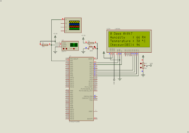
PA0 to PA7 are GPIO outputs connect to a character LCD. The LCD operates in 4-bit mode.

I use its internal RC clock of 8MHz frequency. Optionally we can select an appropriated debugger in the System Core tab.

In this example, the ADC will convert an analog input voltage fed by by a POT connects to PA8. It analog voltage varies between 0 to 3.3V. The conversion result will show on a character LCD.

  1. /* USER CODE BEGIN Header */
  2. /**
  3.   ******************************************************************************
  4.   * @file : main.c
  5.   * @brief : Main program body
  6.   ******************************************************************************
  7.   * @attention
  8.   *
  9.   * <h2><center>&copy; Copyright (c) 2023 STMicroelectronics.
  10.   * All rights reserved.</center></h2>
  11.   *
  12.   * This software component is licensed by ST under BSD 3-Clause license,
  13.   * the "License"; You may not use this file except in compliance with the
  14.   * License. You may obtain a copy of the License at:
  15.   * opensource.org/licenses/BSD-3-Clause
  16.   *
  17.   ******************************************************************************
  18.   */
  19. /* USER CODE END Header */
  20. /* Includes ------------------------------------------------------------------*/
  21. #include "main.h"
  22. #include "lcd4bits.h"
  23.  
  24. /* Private includes ----------------------------------------------------------*/
  25. /* USER CODE BEGIN Includes */
  26.  
  27. /* USER CODE END Includes */
  28.  
  29. /* Private typedef -----------------------------------------------------------*/
  30. /* USER CODE BEGIN PTD */
  31.  
  32. /* USER CODE END PTD */
  33.  
  34. /* Private define ------------------------------------------------------------*/
  35. /* USER CODE BEGIN PD */
  36. /* USER CODE END PD */
  37.  
  38. /* Private macro -------------------------------------------------------------*/
  39. /* USER CODE BEGIN PM */
  40.  
  41. /* USER CODE END PM */
  42.  
  43. /* Private variables ---------------------------------------------------------*/
  44. ADC_HandleTypeDef hadc1;
  45.  
  46. /* USER CODE BEGIN PV */
  47.  
  48. /* USER CODE END PV */
  49.  
  50. /* Private function prototypes -----------------------------------------------*/
  51. void SystemClock_Config(void);
  52. static void MX_GPIO_Init(void);
  53. static void MX_ADC1_Init(void);
  54. /* USER CODE BEGIN PFP */
  55.  
  56. /* USER CODE END PFP */
  57.  
  58. /* Private user code ---------------------------------------------------------*/
  59. /* USER CODE BEGIN 0 */
  60.  
  61. /* USER CODE END 0 */
  62.  
  63. /**
  64.   * @brief The application entry point.
  65.   * @retval int
  66.   */
  67. int main(void)
  68. {
  69. /* USER CODE BEGIN 1 */
  70.  
  71. /* USER CODE END 1 */
  72.  
  73. /* MCU Configuration--------------------------------------------------------*/
  74.  
  75. /* Reset of all peripherals, Initializes the Flash interface and the Systick. */
  76. HAL_Init();
  77.  
  78. /* USER CODE BEGIN Init */
  79.  
  80. /* USER CODE END Init */
  81.  
  82. /* Configure the system clock */
  83. SystemClock_Config();
  84.  
  85. /* USER CODE BEGIN SysInit */
  86.  
  87. /* USER CODE END SysInit */
  88.  
  89. /* Initialize all configured peripherals */
  90. MX_GPIO_Init();
  91. MX_ADC1_Init();
  92. /* USER CODE BEGIN 2 */
  93.  
  94. /* USER CODE END 2 */
  95. lcdInit();
  96. HAL_ADC_Start(&hadc1);
  97. char msg[16];
  98. uint16_t rawValue;
  99. float temp;
  100.  
  101. lcdStr("STM32F103R6 ADC1");
  102. lcdXY(1,2);
  103. lcdStr("And LCD Example");
  104. HAL_Delay(2000);
  105. lcdClear();
  106. lcdCmd(0x0C);
  107.  
  108. /* Infinite loop */
  109. /* USER CODE BEGIN WHILE */
  110. while (1)
  111. {
  112. /* USER CODE END WHILE */
  113. HAL_ADC_PollForConversion(&hadc1,HAL_MAX_DELAY);
  114.  
  115. rawValue=HAL_ADC_GetValue(&hadc1);
  116. temp=((float)rawValue)/4095*3.3;
  117.  
  118. sprintf(msg,"ADC Value: %u",rawValue);
  119. lcdXY(1,1); lcdStr(msg);
  120.  
  121. sprintf(msg,"Voltage: %0.2f V",temp);
  122. lcdXY(1,2); lcdStr(msg);
  123. HAL_Delay(5);
  124.  
  125. /* USER CODE BEGIN 3 */
  126. }
  127. /* USER CODE END 3 */
  128. }
  129.  
  130. /**
  131.   * @brief System Clock Configuration
  132.   * @retval None
  133.   */
  134. void SystemClock_Config(void)
  135. {
  136. RCC_OscInitTypeDef RCC_OscInitStruct = {0};
  137. RCC_ClkInitTypeDef RCC_ClkInitStruct = {0};
  138. RCC_PeriphCLKInitTypeDef PeriphClkInit = {0};
  139.  
  140. /** Initializes the RCC Oscillators according to the specified parameters
  141.   * in the RCC_OscInitTypeDef structure.
  142.   */
  143. RCC_OscInitStruct.OscillatorType = RCC_OSCILLATORTYPE_HSI;
  144. RCC_OscInitStruct.HSIState = RCC_HSI_ON;
  145. RCC_OscInitStruct.HSICalibrationValue = RCC_HSICALIBRATION_DEFAULT;
  146. RCC_OscInitStruct.PLL.PLLState = RCC_PLL_NONE;
  147. if (HAL_RCC_OscConfig(&RCC_OscInitStruct) != HAL_OK)
  148. {
  149. Error_Handler();
  150. }
  151. /** Initializes the CPU, AHB and APB buses clocks
  152.   */
  153. RCC_ClkInitStruct.ClockType = RCC_CLOCKTYPE_HCLK|RCC_CLOCKTYPE_SYSCLK
  154. |RCC_CLOCKTYPE_PCLK1|RCC_CLOCKTYPE_PCLK2;
  155. RCC_ClkInitStruct.SYSCLKSource = RCC_SYSCLKSOURCE_HSI;
  156. RCC_ClkInitStruct.AHBCLKDivider = RCC_SYSCLK_DIV1;
  157. RCC_ClkInitStruct.APB1CLKDivider = RCC_HCLK_DIV1;
  158. RCC_ClkInitStruct.APB2CLKDivider = RCC_HCLK_DIV1;
  159.  
  160. if (HAL_RCC_ClockConfig(&RCC_ClkInitStruct, FLASH_LATENCY_0) != HAL_OK)
  161. {
  162. Error_Handler();
  163. }
  164. PeriphClkInit.PeriphClockSelection = RCC_PERIPHCLK_ADC;
  165. PeriphClkInit.AdcClockSelection = RCC_ADCPCLK2_DIV2;
  166. if (HAL_RCCEx_PeriphCLKConfig(&PeriphClkInit) != HAL_OK)
  167. {
  168. Error_Handler();
  169. }
  170. }
  171.  
  172. /**
  173.   * @brief ADC1 Initialization Function
  174.   * @param None
  175.   * @retval None
  176.   */
  177. static void MX_ADC1_Init(void)
  178. {
  179.  
  180. /* USER CODE BEGIN ADC1_Init 0 */
  181.  
  182. /* USER CODE END ADC1_Init 0 */
  183.  
  184. ADC_ChannelConfTypeDef sConfig = {0};
  185.  
  186. /* USER CODE BEGIN ADC1_Init 1 */
  187.  
  188. /* USER CODE END ADC1_Init 1 */
  189. /** Common config
  190.   */
  191. hadc1.Instance = ADC1;
  192. hadc1.Init.ScanConvMode = ADC_SCAN_DISABLE;
  193. hadc1.Init.ContinuousConvMode = ENABLE;
  194. hadc1.Init.DiscontinuousConvMode = DISABLE;
  195. hadc1.Init.ExternalTrigConv = ADC_SOFTWARE_START;
  196. hadc1.Init.DataAlign = ADC_DATAALIGN_RIGHT;
  197. hadc1.Init.NbrOfConversion = 1;
  198. if (HAL_ADC_Init(&hadc1) != HAL_OK)
  199. {
  200. Error_Handler();
  201. }
  202. /** Configure Regular Channel
  203.   */
  204. sConfig.Channel = ADC_CHANNEL_8;
  205. sConfig.Rank = ADC_REGULAR_RANK_1;
  206. sConfig.SamplingTime = ADC_SAMPLETIME_55CYCLES_5;
  207. if (HAL_ADC_ConfigChannel(&hadc1, &sConfig) != HAL_OK)
  208. {
  209. Error_Handler();
  210. }
  211. /* USER CODE BEGIN ADC1_Init 2 */
  212.  
  213. /* USER CODE END ADC1_Init 2 */
  214.  
  215. }
  216.  
  217. /**
  218.   * @brief GPIO Initialization Function
  219.   * @param None
  220.   * @retval None
  221.   */
  222. static void MX_GPIO_Init(void)
  223. {
  224. GPIO_InitTypeDef GPIO_InitStruct = {0};
  225.  
  226. /* GPIO Ports Clock Enable */
  227. __HAL_RCC_GPIOA_CLK_ENABLE();
  228. __HAL_RCC_GPIOB_CLK_ENABLE();
  229.  
  230. /*Configure GPIO pin Output Level */
  231. HAL_GPIO_WritePin(GPIOA, GPIO_PIN_0|GPIO_PIN_1|GPIO_PIN_2|GPIO_PIN_3
  232. |GPIO_PIN_4|GPIO_PIN_5|GPIO_PIN_6|GPIO_PIN_7, GPIO_PIN_RESET);
  233.  
  234. /*Configure GPIO pins : PA0 PA1 PA2 PA3
  235.   PA4 PA5 PA6 PA7 */
  236. GPIO_InitStruct.Pin = GPIO_PIN_0|GPIO_PIN_1|GPIO_PIN_2|GPIO_PIN_3
  237. |GPIO_PIN_4|GPIO_PIN_5|GPIO_PIN_6|GPIO_PIN_7;
  238. GPIO_InitStruct.Mode = GPIO_MODE_OUTPUT_PP;
  239. GPIO_InitStruct.Pull = GPIO_NOPULL;
  240. GPIO_InitStruct.Speed = GPIO_SPEED_FREQ_LOW;
  241. HAL_GPIO_Init(GPIOA, &GPIO_InitStruct);
  242.  
  243. }
  244.  
  245. /* USER CODE BEGIN 4 */
  246.  
  247. /* USER CODE END 4 */
  248.  
  249. /**
  250.   * @brief This function is executed in case of error occurrence.
  251.   * @retval None
  252.   */
  253. void Error_Handler(void)
  254. {
  255. /* USER CODE BEGIN Error_Handler_Debug */
  256. /* User can add his own implementation to report the HAL error return state */
  257. __disable_irq();
  258. while (1)
  259. {
  260. }
  261. /* USER CODE END Error_Handler_Debug */
  262. }
  263.  
  264. #ifdef USE_FULL_ASSERT
  265. /**
  266.   * @brief Reports the name of the source file and the source line number
  267.   * where the assert_param error has occurred.
  268.   * @param file: pointer to the source file name
  269.   * @param line: assert_param error line source number
  270.   * @retval None
  271.   */
  272. void assert_failed(uint8_t *file, uint32_t line)
  273. {
  274. /* USER CODE BEGIN 6 */
  275. /* User can add his own implementation to report the file name and line number,
  276.   ex: printf("Wrong parameters value: file %s on line %d\r\n", file, line) */
  277. /* USER CODE END 6 */
  278. }
  279. #endif /* USE_FULL_ASSERT */
  280.  
  281. /************************ (C) COPYRIGHT STMicroelectronics *****END OF FILE****/
  282.   

If you have any doubt with LCD Interfacing with STM32 please see this post. Click here to download its source file.