Friday, September 30, 2022

Making A DIY SN74HC595 Serial 10-Digit 7-Segment Display Board

Shift Registers are very useful for expanding the controller I/O ports. However driving a dot matrix display, or multiple seven-segment display also need this kind of chip. Because only multiplexing could not achieve a good displaying task.

Making A DIY SN74HC595 Serial 10-Digit 7-Segment Display Board
Eight-Digit and Ten-Digit Serial Seven-Segment Display Using SN74HC595N

It's not important to make any DIY display like this. But I have many common-cathode type seven-segments display, SN74HC595N shift registers, copper clad board, etc. So I want to use them all rather than keep them new in my own repair shop.

The design was complicated due to multiple count of connection between register to register, and register to display. So I tried to eliminate some components especially the current cutting resistors.

The shift register chip output pin voltage is +5V while the display need around 2V to operate. Without using dozens of current cutting resistors, I reduce the voltage by making voltage division. I add 3 rectifier diodes in series with each common cathodes of the display to divide the voltage.

Eight-Digit Seven-Segment Display

For the first time I design, I was unwilling to do this task due to difficulty in PCB fabrication, and laser printing toner problem. Because the ink cartridge was old. So I only made an 8-digit display.

Making A DIY SN74HC595 Serial 10-Digit 7-Segment Display Board
Arduino Test Program

 I use Proteus 8.10 to design the schematic and PCB.

Making A DIY SN74HC595 Serial 10-Digit 7-Segment Display Board
Schematic Design
PCB contains a lot of wire connections due to a large amount of registers an displays. It seems to be a double side PCB, but I use jumper wire instead.
 

Making A DIY SN74HC595 Serial 10-Digit 7-Segment Display Board

PCB View In Proteus

I previewed this design in 3D viewer. Most of components are lack of 3D packages.

Making A DIY SN74HC595 Serial 10-Digit 7-Segment Display Board
Design 3D View
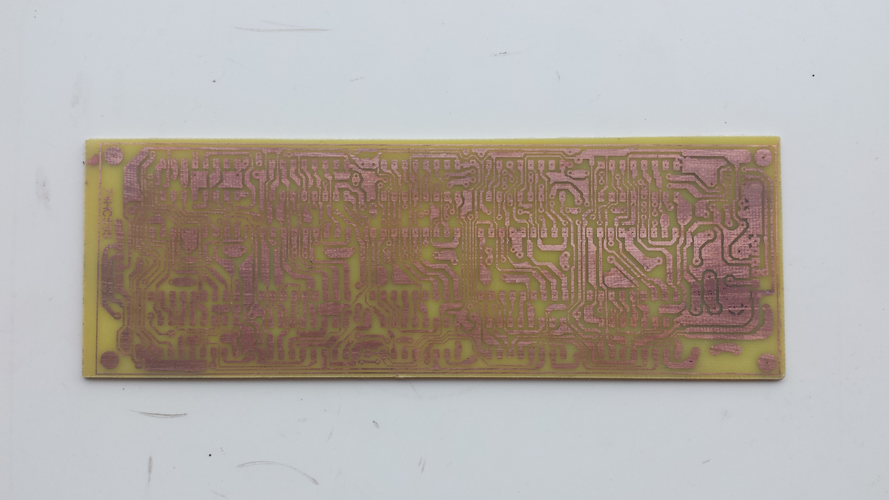
I use toner transfer method to make this DIY PCB. Using sing any online PCB order cost around 10 US Dollars excluding shipping cost. However it is not necessary here.


Making A DIY SN74HC595 Serial 10-Digit 7-Segment Display Board
Component Side Label Transferring

Making A DIY SN74HC595 Serial 10-Digit 7-Segment Display Board
Copper Side After Etching

Making A DIY SN74HC595 Serial 10-Digit 7-Segment Display Board
Copper Side After Soldering

Making A DIY SN74HC595 Serial 10-Digit 7-Segment Display Board
Copper Side Before Etching
I spent one day to finish this DIY electronic hobby project.


Making A DIY SN74HC595 Serial 10-Digit 7-Segment Display Board
Finished PCBA Assembling

It works well but the display doesn't have Dot Point.

Making A DIY SN74HC595 Serial 10-Digit 7-Segment Display Board
I firstly test this PCBA With Arduino Program Due To Ease Of Use.

I store this design file in Github.

Arduino Test Program #1 Using SPI

#include <SPI.h>
 
 
void setup() {
  // put your setup code here, to run once:
  SPI.begin();
  pinMode(10,OUTPUT);
 
 
}
 
void loop() {
  // put your main code here, to run repeatedly:
 digitalWrite(10,LOW);
  SPI.transfer(0x3F);
  SPI.transfer(0x06);
  SPI.transfer(0x5B);
  SPI.transfer(0x4F);
  SPI.transfer(0x6D);
  SPI.transfer(0x7D);
  SPI.transfer(0x07);
  SPI.transfer(0x7F);
  digitalWrite(10,HIGH);
  delay(3000);
}

Arduino Test Program #2


#include <SPI.h>
 
unsigned char ssd[16]={0x3F,0x06,0x5B,0x4F,0x66,0x6D,0x7D,0x07,0x7F,0x6F,
                      0x77,0x7C,0x39,0x5E,0x79,0x71};
 
unsigned char msg1[10]={0x08,0x08,0x76,0x79,0x38,0x38,0x5C,0x08,0x08,0x08};
void setup() {
  // put your setup code here, to run once:
  SPI.begin();
  pinMode(10,OUTPUT);
}
 
void loop() {
  // put your main code here, to run repeatedly:
  /*
 digitalWrite(10,LOW);
 
  for(int i=9;i>=0;i--)
    SPI.transfer(ssd[i]);
  digitalWrite(10,HIGH); 
  delay(5000);
 
  digitalWrite(10,LOW);
 
  for(int i=15;i>=10;i--)
    SPI.transfer(ssd[i]);
  digitalWrite(10,HIGH); 
  delay(5000);
  */

   for(int i=9;i>=0;i--){
   digitalWrite(10,LOW);
 
  SPI.transfer(msg1[i]);
  delay(1000);
  digitalWrite(10,HIGH); 
   }
}

Eight-Digit Seven-Segment Display

I add two more digits to previous design. The PCB design is  quit bigger.

Making A DIY SN74HC595 Serial 10-Digit 7-Segment Display Board

Making A DIY SN74HC595 Serial 10-Digit 7-Segment Display Board

Making A DIY SN74HC595 Serial 10-Digit 7-Segment Display Board

Making A DIY SN74HC595 Serial 10-Digit 7-Segment Display Board

Making A DIY SN74HC595 Serial 10-Digit 7-Segment Display Board

Making A DIY SN74HC595 Serial 10-Digit 7-Segment Display Board

Making A DIY SN74HC595 Serial 10-Digit 7-Segment Display Board

Making A DIY SN74HC595 Serial 10-Digit 7-Segment Display Board

Making A DIY SN74HC595 Serial 10-Digit 7-Segment Display Board

Making A DIY SN74HC595 Serial 10-Digit 7-Segment Display Board

Making A DIY SN74HC595 Serial 10-Digit 7-Segment Display Board

Making A DIY SN74HC595 Serial 10-Digit 7-Segment Display Board

Making A DIY SN74HC595 Serial 10-Digit 7-Segment Display Board

Making A DIY SN74HC595 Serial 10-Digit 7-Segment Display Board


Making A DIY SN74HC595 Serial 10-Digit 7-Segment Display Board
Arduino Test Program

 Arduino Test Program for this PCBA

or #include <SPI.h>
 
unsigned char ssd[16]={0x3F,0x06,0x5B,0x4F,0x66,0x6D,0x7D,0x07,0x7F,0x6F,
                      0x77,0x7C,0x39,0x5E,0x79,0x71};
void setup() {
  // put your setup code here, to run once:
  SPI.begin();
  pinMode(10,OUTPUT);
 
 
}
 
void loop() {
  // put your main code here, to run repeatedly:
 digitalWrite(10,LOW);
 /*
  SPI.transfer(ssd[0]);
  SPI.transfer(ssd[1]);
 
  SPI.transfer(ssd[2]);
  SPI.transfer(ssd[3]);
 
  SPI.transfer(ssd[4]);
  SPI.transfer(ssd[5]);
 
  SPI.transfer(ssd[6]);
  SPI.transfer(ssd[7]);
 
  SPI.transfer(ssd[8]);
  SPI.transfer(ssd[9]);
  */

  for(int i=9;i>=0;i--)
    SPI.transfer(ssd[i]);
  digitalWrite(10,HIGH); 
  delay(5000);
 
  digitalWrite(10,LOW);
 
  for(int i=15;i>=10;i--)
    SPI.transfer(ssd[i]);
  digitalWrite(10,HIGH); 
  delay(5000);
}

Click here to download load this PCBA design file. 


Tuesday, October 13, 2020

STM32F103R6 SPI Interfaces To SN74HC595N Character LCD Driver

In previous post, I show an example of driving a HD44780-based character LCD using 4-bit data mode. Driving this LCD module is quite easy. We can use other driving chip to make the communication interface between the micro-controller and this LCD module simpler. For example the programmer can add a I2C I/O expanding chip (PCF8574), or an SPI I/O expanding chip (SN74HC595N or 74HC164).

STM32F103R6 SPI Interfaces To SN74HC595N Character LCD Driver

Simulating Program Using Proteus VSM 8.15

In this example, I use an SN74HC595N serial-in-parallel-out shift registers to drive a character LCD. This chip uses the Serial Peripheral Interface (SPI). The LCD module is a 20x4 HD44780-based LCD controller.

STM32F103R6 SPI Interfaces To SN74HC595N Character LCD Driver

Device Configuration Tool For SPI1 Communication Module


We need to configure the SPI1 communication module of this micro-controller as above. I choose the slave select or the Hardware NSS output signal using hardware. So we don't need to write the slave select signal in program. This signal is automatic activate after the SPI data has transmitted. 

  1. /* USER CODE BEGIN Header */
  2. /**
  3.   ******************************************************************************
  4.   * @file : main.c
  5.   * @brief : Main program body
  6.   ******************************************************************************
  7.   * @attention
  8.   *
  9.   * <h2><center>&copy; Copyright (c) 2023 STMicroelectronics.
  10.   * All rights reserved.</center></h2>
  11.   *
  12.   * This software component is licensed by ST under BSD 3-Clause license,
  13.   * the "License"; You may not use this file except in compliance with the
  14.   * License. You may obtain a copy of the License at:
  15.   * opensource.org/licenses/BSD-3-Clause
  16.   *
  17.   ******************************************************************************
  18.   */
  19. /* USER CODE END Header */
  20. /* Includes ------------------------------------------------------------------*/
  21. #include "main.h"
  22.  
  23. /* Private variables ---------------------------------------------------------*/
  24. SPI_HandleTypeDef hspi1;
  25.  
  26. /* Private function prototypes -----------------------------------------------*/
  27. void SystemClock_Config(void);
  28. static void MX_GPIO_Init(void);
  29. static void MX_SPI1_Init(void);
  30.  
  31. uint8_t DPORT;
  32.  
  33. void delay1(uint16_t dTime){
  34. for(uint16_t i=0;i<dTime;i++);
  35. }
  36.  
  37. void delay2(uint8_t dTime){
  38. for(uint8_t i=0;i<dTime;i++) delay1(5000);
  39. }
  40.  
  41. void lcdCmd(uint8_t cmd){
  42. uint8_t temp=0x02;
  43. DPORT=temp|(cmd&0xF0);
  44. HAL_SPI_Transmit(&hspi1,&DPORT,1,10);
  45. delay1(10);
  46. temp=0;
  47. DPORT=temp|(cmd&0xF0);
  48. HAL_SPI_Transmit(&hspi1,&DPORT,1,10);
  49. delay1(100);
  50.  
  51. temp=0x02;
  52. DPORT=temp|(cmd<<4);
  53. HAL_SPI_Transmit(&hspi1,&DPORT,1,10);
  54. delay1(10);
  55. temp=0;
  56. DPORT=temp|(cmd<<4);
  57. HAL_SPI_Transmit(&hspi1,&DPORT,1,10);
  58. }
  59.  
  60. void lcdDat(uint8_t dat){
  61. uint8_t temp=0x03;
  62. DPORT=temp|(dat&0xF0);
  63. HAL_SPI_Transmit(&hspi1,&DPORT,1,10);
  64. delay1(10);
  65. temp=0x01;
  66. DPORT=temp|(dat&0xF0);
  67. HAL_SPI_Transmit(&hspi1,&DPORT,1,10);
  68. delay1(100);
  69.  
  70. temp=0x03;
  71. DPORT=temp|(dat<<4);
  72. HAL_SPI_Transmit(&hspi1,&DPORT,1,10);
  73. delay1(10);
  74. temp=0x01;
  75. DPORT=temp|(dat<<4);
  76. HAL_SPI_Transmit(&hspi1,&DPORT,1,10);
  77. }
  78.  
  79. void lcdInit(void){
  80. DPORT=0x00;
  81. delay1(2000);
  82. lcdCmd(0x33);
  83. delay1(100);
  84. lcdCmd(0x32);
  85. delay1(100);
  86. lcdCmd(0x28);
  87. delay1(100);
  88. lcdCmd(0x0F);
  89. delay1(100);
  90. lcdCmd(0x01);
  91. delay1(2000);
  92. lcdCmd(0x06);
  93. delay1(100);
  94. }
  95.  
  96. void lcdStr(uint8_t *str){
  97. while(*str) lcdDat(*str++);
  98. }
  99.  
  100. void lcdXY(uint8_t x,uint8_t y){
  101. // 20x4 LCD
  102. uint8_t tbe[]={0x80,0xC0,0x94,0xD4};
  103. lcdCmd(tbe[y-1]+x-1);
  104. delay1(100);
  105. }
  106.  
  107. void lcdClear(void){
  108. lcdCmd(0x01);
  109. delay1(100);
  110. }
  111.  
  112. /**
  113.   * @brief The application entry point.
  114.   * @retval int
  115.   */
  116. int main(void)
  117. {
  118.  
  119. /* Reset of all peripherals, Initializes the Flash interface and the Systick. */
  120. HAL_Init();
  121.  
  122. /* Configure the system clock */
  123. SystemClock_Config();
  124.  
  125. /* Initialize all configured peripherals */
  126. MX_GPIO_Init();
  127. MX_SPI1_Init();
  128.  
  129. lcdInit();
  130. lcdClear();
  131. delay2(50);
  132.  
  133. lcdXY(5,1);
  134. lcdStr("Hello World!");
  135. delay2(50);
  136.  
  137. lcdXY(1,2);
  138. lcdStr("STM32F103R6Tx ARM");
  139. delay2(50);
  140.  
  141. lcdXY(1,3);
  142. lcdStr("SPI Interfaces To");
  143. delay2(50);
  144.  
  145. lcdXY(1,4);
  146. lcdStr("SN74HC595N Serial In");
  147. delay2(50);
  148.  
  149. lcdClear();
  150. lcdXY(1,1);
  151. lcdStr("Parallel Out Shift");
  152. delay2(50);
  153. lcdXY(1,2);
  154. lcdStr("Registers And 20x4");
  155. delay2(50);
  156. lcdXY(1,3);
  157. lcdStr("HD44780 Character");
  158. delay2(50);
  159. lcdXY(1,4);
  160. lcdStr("LCD Display Driving ");
  161. /* Infinite loop */
  162. /* USER CODE BEGIN WHILE */
  163. while (1)
  164. {
  165.  
  166. }
  167. }
  168.  
  169. /**
  170.   * @brief System Clock Configuration
  171.   * @retval None
  172.   */
  173. void SystemClock_Config(void)
  174. {
  175. RCC_OscInitTypeDef RCC_OscInitStruct = {0};
  176. RCC_ClkInitTypeDef RCC_ClkInitStruct = {0};
  177.  
  178. /** Initializes the RCC Oscillators according to the specified parameters
  179.   * in the RCC_OscInitTypeDef structure.
  180.   */
  181. RCC_OscInitStruct.OscillatorType = RCC_OSCILLATORTYPE_HSI;
  182. RCC_OscInitStruct.HSIState = RCC_HSI_ON;
  183. RCC_OscInitStruct.HSICalibrationValue = RCC_HSICALIBRATION_DEFAULT;
  184. RCC_OscInitStruct.PLL.PLLState = RCC_PLL_NONE;
  185. if (HAL_RCC_OscConfig(&RCC_OscInitStruct) != HAL_OK)
  186. {
  187. Error_Handler();
  188. }
  189. /** Initializes the CPU, AHB and APB buses clocks
  190.   */
  191. RCC_ClkInitStruct.ClockType = RCC_CLOCKTYPE_HCLK|RCC_CLOCKTYPE_SYSCLK
  192. |RCC_CLOCKTYPE_PCLK1|RCC_CLOCKTYPE_PCLK2;
  193. RCC_ClkInitStruct.SYSCLKSource = RCC_SYSCLKSOURCE_HSI;
  194. RCC_ClkInitStruct.AHBCLKDivider = RCC_SYSCLK_DIV1;
  195. RCC_ClkInitStruct.APB1CLKDivider = RCC_HCLK_DIV1;
  196. RCC_ClkInitStruct.APB2CLKDivider = RCC_HCLK_DIV1;
  197.  
  198. if (HAL_RCC_ClockConfig(&RCC_ClkInitStruct, FLASH_LATENCY_0) != HAL_OK)
  199. {
  200. Error_Handler();
  201. }
  202. }
  203.  
  204. /**
  205.   * @brief SPI1 Initialization Function
  206.   * @param None
  207.   * @retval None
  208.   */
  209. static void MX_SPI1_Init(void)
  210. {
  211.  
  212. /* USER CODE BEGIN SPI1_Init 0 */
  213.  
  214. /* USER CODE END SPI1_Init 0 */
  215.  
  216. /* USER CODE BEGIN SPI1_Init 1 */
  217.  
  218. /* USER CODE END SPI1_Init 1 */
  219. /* SPI1 parameter configuration*/
  220. hspi1.Instance = SPI1;
  221. hspi1.Init.Mode = SPI_MODE_MASTER;
  222. hspi1.Init.Direction = SPI_DIRECTION_2LINES;
  223. hspi1.Init.DataSize = SPI_DATASIZE_8BIT;
  224. hspi1.Init.CLKPolarity = SPI_POLARITY_LOW;
  225. hspi1.Init.CLKPhase = SPI_PHASE_1EDGE;
  226. hspi1.Init.NSS = SPI_NSS_HARD_OUTPUT;
  227. hspi1.Init.BaudRatePrescaler = SPI_BAUDRATEPRESCALER_128;
  228. hspi1.Init.FirstBit = SPI_FIRSTBIT_MSB;
  229. hspi1.Init.TIMode = SPI_TIMODE_DISABLE;
  230. hspi1.Init.CRCCalculation = SPI_CRCCALCULATION_DISABLE;
  231. hspi1.Init.CRCPolynomial = 10;
  232. if (HAL_SPI_Init(&hspi1) != HAL_OK)
  233. {
  234. Error_Handler();
  235. }
  236. /* USER CODE BEGIN SPI1_Init 2 */
  237.  
  238. /* USER CODE END SPI1_Init 2 */
  239.  
  240. }
  241.  
  242. /**
  243.   * @brief GPIO Initialization Function
  244.   * @param None
  245.   * @retval None
  246.   */
  247. static void MX_GPIO_Init(void)
  248. {
  249.  
  250. /* GPIO Ports Clock Enable */
  251. __HAL_RCC_GPIOA_CLK_ENABLE();
  252.  
  253. }
  254.  
  255. /* USER CODE BEGIN 4 */
  256.  
  257. /* USER CODE END 4 */
  258.  
  259. /**
  260.   * @brief This function is executed in case of error occurrence.
  261.   * @retval None
  262.   */
  263. void Error_Handler(void)
  264. {
  265. /* USER CODE BEGIN Error_Handler_Debug */
  266. /* User can add his own implementation to report the HAL error return state */
  267. __disable_irq();
  268. while (1)
  269. {
  270. }
  271. /* USER CODE END Error_Handler_Debug */
  272. }
  273.  
  274. #ifdef USE_FULL_ASSERT
  275. /**
  276.   * @brief Reports the name of the source file and the source line number
  277.   * where the assert_param error has occurred.
  278.   * @param file: pointer to the source file name
  279.   * @param line: assert_param error line source number
  280.   * @retval None
  281.   */
  282. void assert_failed(uint8_t *file, uint32_t line)
  283. {
  284. /* USER CODE BEGIN 6 */
  285. /* User can add his own implementation to report the file name and line number,
  286.   ex: printf("Wrong parameters value: file %s on line %d\r\n", file, line) */
  287. /* USER CODE END 6 */
  288. }
  289. #endif /* USE_FULL_ASSERT */
  290.  
  291. /************************ (C) COPYRIGHT STMicroelectronics *****END OF FILE****/
  292.  

Its source code is very simple. It's similar to the previous example. We just process the 4-bit LCD controlling. Then we will need to put those LCD controlling data into the SPI1 data buffer before it's sent over the SPI communication interface. 


If we want to use the 74HC164 serial-in-parallel-out shift registers we will need to drive the LCD Enable pin directly from the micro-controller. Click here to download its source file.